-
3D Printed Thermoforming Tools Overview
If you have any questions about this application or are looking for which 3D printer would be the best fit for thermoforming please contact our team. If you are looking to have 3D printed thermoforming tools manufactured you can have them made at our 3D printing service bureau.
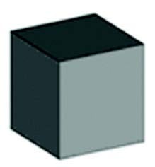
Custom tools directly from CAD models are provided by FDM patterns. Interior fills have the ability to be processed with varying levels of porosity when using Insight. This is so that vacuum’s can be pulled throughout the tool without the need for drilling vacuum-assist holes. Both CAD data and FDM give the ability to coordinate tooling solutions for thermoforming. This is made possible by coordinating the parent geometry to output forming tools, scribe or offset trim tools, and vacuum-holding jigs.
-
CAD Considerations
Shrinkage
The most common types of forming plastics happen to contain some level of shrinkage during the thermoforming process. It’s highly suggested that shrink compensation is applied during the tool design stages. If or when the native CAD file is not available, the STL file can be scaled in order to provide necessary compensation. Keep in mind that mold shrinkage for male molds is 0.4%-0.6% and female molds is 0.5%-0.7%.
Drafting Walls
Something to consider is to draft side walls in order to properly assist tool extraction. A minimum draft of 1-3 degrees should be designed into the tool. Additional drafting of angles 5-7 degrees, as well as the added benefit of minimizing the likelihood of webbing, tens to also assist the tooling extraction.Radius
The minimum required radius for tool design typically equals to the nominal thickness, which is 0.71 mm (0.028″ in) thickness
CAD Output files
The CAD output files will still be in STL format. When using a simple model. surfaces have the ability to be approximated with twelve triangles, two on each side. More triangles are produced as the surface becomes more complex.
STL files should be exported as binary
Settings
Has your part come out rougher or smoother than expected? If so, it’s possible to change the angle, deviation and chord height in order to create the correct outcome. Faceting is determined by the relative coarseness of curved areas of the adjoining triangles. Deviation, chord height, angle control or angle tolerance are all common variables of faceting. Coarse faceting is commonly caused by the angle setting being too high, or the deviation/chord height settings being too large, or a mixture of both.Benefits
The CAD design of the tool can have several benefits incorporated to both build time and material cost savings. Automatic support generation is provided by Insight’s preprocessing software.This calculation scans the geometry and automatically generates support structures needed to build geometry such as cavities and overhanging structures.Tools tend to be build out of solid materials when thermoforming. Howvever, this isn’t required when building with FDM. It can only be optimized through certain processing styles, such as designing in ribbing, and using Insight Sparse-fill build style. -
Tool Design Optimization & Considerations
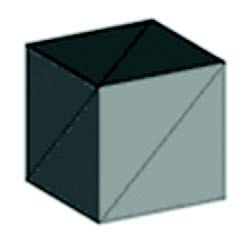
Tool optimization using Ribbing
Using the CAD program, Finite Element Analysis (FEA) of the tooling design, this is also the best way to calculate potential tool deflection under forming loads. Most thermoforming machines have the ability to achieve -25-28inHg when using the conversion -inHg to PSI. This would equal to 15 PSI which could potentially be used to calculate the pressure load on the surfaces pf the tool in the analysis tool. Life expectancy, as well as whether the tool will be fixtured in the framing system of the thermoforming machine, or free float on the bottom of the page, could have potential influences on tool design. 0.25-in. ribs and walls are recommended for tools that will be fixtured in a forming machine. Rib spacing is often a complex parameter that is geometry depended. The use of FEA tools is recommended in order to optimize spacing requirements. Rib structures should be placed on a 1-in. centerline space when working with a conservative structure. As a general rule, spacing can be increased as tool height and surface area will be reducedTool Fixturing
Hardware inserts or hard points for drilling and tapping locations should be accounted for in the CAD desgin of the tool. This should only be done if the tool will be fixtured into the framing system of the thermoforming machine. Pausing during the build is possible in the FDM process. This is to allow the insertion of nuts or other fastening hardware. A reminder that higher temperature with FDM materials such as PC, ULTEM 9085 and PPSF typically show a witness line of a shrink point at the insertion point on the part due to temperature fluctuation of the build envelope during instertion. Another thing to be aware of is insertion shouldn’t be practiced if high tool accuracy is required. Tools built with PPSF shouldn’t include insertion. There’s high potential of the foundation sheet to loose vacuum during insertion because of high temperature change. -
Insight Process
So why use FDM tools? The main benefit of using FDM tools is because of the ability of the tool to be processed and build with porosity throughout the entire tool. When using traditional tools, drilling vacuum-assist holes throughout the tool to allow for vacuum transfer through the tool is required. This is automated with the Insight software and the processing stule of building with positive air gaps in the raster fills throughout the build when using FDM. This enables channels throughout the entire tool for the vacuum to be drawn through. If an FEA tool isn’t used in the design of the tool to calculate surface loads, the best recommendation to ensure tool integrity, would be to process the tool using in Insight using the ‘part Interior Style’ of Solid-normal under ‘Modeler Setup’. Then, you can add the internal porosity through one of two methods.
- Select Setup in the Toolpaths main menu, and, click in the advanced parameters button. After opening this menu, locate the internal raster airgap parameter and set it to +0.010 in. (+0.254 mm). This parameter is important because it allows vacuum to be pulled throughout the tool.
- Another way to build porosity into the tool build is through custom groups. Select ‘New button’ under the Toolpath menu. Then, go under ‘Air gap between,’ and enter +0.010 in. (+0.254 mm) in the Adjacent rasters box.
After choosing one of the two options above, select alll curves on the model so they become highlighted on the screen. Furthermore, click the “Add” button under the Custom groups menu. Additional information about this feature can be found by simply searching “custom groups” in the Help menu.
System Mode Selections with ULTEM Material
The ‘Normal System Mode’ should be used when building tools. This is because increased oven temperature is allowed to prevent part curling from the base.
Processing With PPSF Material
It’s highly recommended that “Auto Cool Down” mode on the FDM machine is used with PPSF material. This is to prevent temperature shock to the tool during removal, which at times could end in fracturing.
-
Post Processing FDM Tool
Light sanding is typically the only thing needed when post processing FDM tools. All tools which are used for test in this application were sanded with 120-grit aluminum oxide sand paper using a 5.5-in. dual-action sander. The main focus when sanding was blending the area of the seam to match the adjacent surfaces.
Fillers
When using fillers, the FDM tool’s natural porosity is blocked. Avoid using them if possible.
-
Release Sprays
Two types of release sprays were used during the testing process
- The first was Sprayon S00206, an all purpose silicone lubricant. FDM materials that were tested came out positively. A light coat was sprayed on the tool on every other pull.
- Sprayon S00708 was release tested and formulated with P.T.F.E. It was found to release better than silicone formula on all FDM materials tested. Once again. a light coat was sprayed on the tool on every other pull.
- Other untested considerations could be Zyvax and Miller Stephenson.
-
Testing
Testing and thermoforming design expertise was in partnership with Kintz Plastic Inc., Howes Cave, New York.
Kydex
All test pulls were made with Kyndex T in 0.250 in. (6.35 mm) sheet stock. Kydex T is a fire-retardant thermoplastic sheet for general thermoforming, most frequently used used in aerospace applications. Drying is only necessary in high humidity. If the material If the material requires drying, its recommended it be dried at 68 C (155 F), or 15 C below product’s HDT for 16 hours for 3.20 mm (0.125 in.) thickness. Two sided heaters are recommended above 2.00 mm (0.080 in.) nominal thickness. Additional Kydex material information can be found at www.kydex.com/technical-data/technical-briefs.aspx.
Tests were processed with Kydex T in 0.250 in. (6.35 mm) sheet stock. Kydex T is a fire-retardent thermoplastic sheet used for general thermoforming. It’s often used in aerospace applications. Drying is usually not needed unless dealign with high humidity. If the material requires drying, it should be deied at 68 C (155F) or 15C below the products’ HDT for 16 hours for 3.20 mm (0.125 in.) thickness. Two-sided heaters are necessary above 2.00 mm (0.080 in.) normal thickness. Additonal Kydex material information can be found at www.kydex.com/technical-data/technical-briefs.aspx.
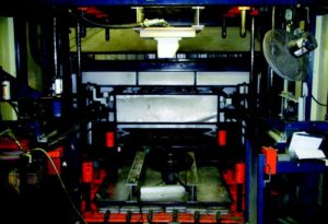
Tests pulls were processed on a Monark SPF Series thermoformer with LP heating. The Monark system uses a top and bottom heater which allow for more uniform heating of the plastic sheet.
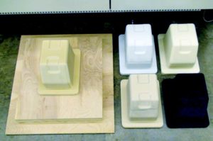
Test tools were inverted and mounted on the top frame of the machine in order to allow for the natural draping of the heated plastic to compliment the deep draw. This assists in minimizing chill spots on the pulls by reducing the time of contract between the sheet and the tool, prior to vacuum being pulled. The FDM tool was then bolted to a plywood base that consisted of 5 layers of 0.75 in. plywood. The plywood was glued and screwed together to coordinate with the thermoforming framework. This configuration enabled the tool to be extracted from the sheet form using pneumatic lift of the machine, once the plastic bad cooled. The configuration duplicated a production setup. This means repeat processing of the tool was allowed.
-
FDM Tooling Materials
Material # Of Pulls Notes ABS M30 1 – Failure Sheet bonded to ABSM30 tool PCABS 1 PC 1 ULTEM 9085 12 7 successful pulls performed on the tool successfully (first 5 pulls used to set up production, all pulls successful with slight webbing in finished forms) PPSF 3 During third pull, hardware inserts were pulled out of the tool during tool extraction * Note: There were minimal adhesion between sheet material and tool. This means the tool material isn’t expected to have failed with regards to temperature. A mixture of tool design for the insert locations and/or a problem if repeated thermo cycling of the PPSF material resulting in decreasing material properties, are presumed to be causes for the tool failure. PPSF material is a compatible material for thermoforming due to high temperature capabilities. However it is not recommended for use with mechanical extraction machines. Instead, practice manual tool extraction.
-
Processing Times & Temperatures
Located below is a program of times and temperatures that were used on the Monark SPF thermoforming machine. the same times and temperatures were used for all the FDM tooling materials.
Heating the Sheet
Kydex sheets were heated for about 230 seconds The temperature when removed from the oven jsut prior to draping over the tool and pulling vacuum was 180C +/-5. Vacuum was then applied in order to lessen the chance for webbing in the corners of the tool. This was done gradually. It’s recommended that the geometry which incorporates deep draws, utilizes an additional “web killer” fixture. This is a secondary frame tool that is offset from the largest footprint of the tool. The tool aid is then used to pre-stretch the hot plastic down to the tool base before the pulling vacuum.
Cooling the Sheet After Aookying Vacuum
20-30 seconds after pulling the vacuum, cooling fans turn on to help cool the sheet faster
300 seconds were used in the cool down program prior to releasing vacuum on the tool
Tool Extraction
To help with the automated tool extraction, air pressure between 20 and 30 PSI was applied o the tool before any movement of the table. Use caution when applying pressure to the tools to prevent possible rupture of tool and form. Pressure should be applied slowly. Typically, a slight expansion of the walls of the form will appear during pressurization. This allows air to move apart from the area between the sheet and tool. After about two or three air bursts were applied, the table was slowly raised, thus allowing the tool to be extracted from the sheet.
-
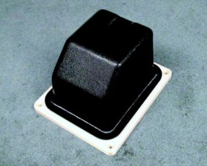
Successive Processing of the ULTEM 9085 Tool
Seven successful pulls were performed usign the progra descreibed above. The ULTEM 9085 tool wasn’t cooled with any additional time or oother cooling methofs between pulls. The goal was to duplciate the short-run production scenario using a single-station thermoforming machine. The temperature of the tool was recoreded before draping the hot sheet plastic and drawing vacuum, then again after tool extraction for each pull. The chart below shows the recorded temperatures.
Pull Pre-pull Tool Temperature Post-pull Tool Temperature 1 51°C 60°C 2 55°C 66°C 3 53°C 67°C 4 53°C 71°C 5 52°C 72°C 6 57°C 75°C 7 57°C 73°C -
Testing Summary
Besides ABS M30, all FDM materials were able to successfully pull and extract the tool for a minimum of one thermoformed part. All parts did exhibit some level of webbing in the corners of the formed parts. The press operater was confident that the webbing could be eliminated wotj the addition of a “web killer” fixture. It’s suggested that PC and PCABS material is used ffor lower temperature materials anf single wuality formings.
PPSF maaterial ended with well results regqarding temoerature compatibility, however exhibited tool failure during extraction on the third forming. Several factors or combinations of factors could have influenced the failure. Tool desin with regard to the solid wall thickness before the hardware inserts were places could be lengthened to allow for more material strength. Furthermore, material strength may have reduced because of temoerature cycling during the forming process. Additonal testing is required to better understand this theory.
ULTEM 9085 performed the best out of all other materials. A total of 12 tests were performed. All mechanical tool extraction by the forming machine demed to be successfil with no observed damage to the tool. Before beginning, five tests were processed on the tool before swapping te tool out to test other FDM materials. The tool was then reconctructed om tjhe machine and an additonal secen pulls were made without anty additioonal cooling time between pulls. This was done to test teh ability for the tool to perform in a traditional production environemnt and test cycle time of the tool and process. Results ended in as good ot better processing time as traditional tooling materials. No additional cooling devices (watter channels or coolers) were used with any of the FDM tools. The capability to proces the FDM tools using internal proosity is made to emable the tool to not abosorb the heat transfer during the forming process as fast as traditional materials. This also results in the tool being able to cool wuicker with only air cooling by fans.
If hardware or fasteners are to be integrated into the tool using pause commands entered during the Insight pre-processing, its recommended to design 3-4 tmes the wall thickness of solid material wall prior hardware embedment. Again, its important to reiterate that inserting of hardware pr fasteners in PPSF tools is not suggested. Also note that this testing was performed with one geometry and one production style forming machine. Results oculd vary depending on the geometry, equipment, material, type, and forming encironments.
- Company
- Products
- Manufacturing Services
- Resources
- Why Silicone 3D Printing?
- Fuse 1 | SLS Design Guidelines
- Technical Support, Repairs for 3D Printing, CNC Milling, 3D Scanning
- Terms and Conditions – Annual Maintenance Contract Proto3000
- Billable Technical Support & Repair Services
- Proto3000 Webinar Series
Skip to content

Technical Application Guide – Thermoforming with 3D Printing
Home Technical Application Guide – Thermoforming with 3D Printing