-
Introduction
Bound Metal Deposition
The Studio System™ is a three-step solution that automates metal 3D printing. Integrated through Desktop Metal’s cloud-based software, it delivers a seamless workflow for printing complex parts in-house—from digital file to sintered part.
Print
The Studio System printer uses Bound Metal Deposition™ or BMD™. BMD is similar to one of the most widely-used 3D printing technologies, Fused Filament Fabrication, FFF. Instead of a filament, the Studio System uses bound metal rods—metal powder held together by wax and a polymer binder. The rods are fed through a heated extruder onto the build plate. The printer shapes the part layer by layer, line by line — producing a printed part, or ”green part.”Debind
The green part is then placed into the debinder, immersed in proprietary debind fluid, dissolving the primary binder and creating an open-pore channel structure to prepare the part for sintering. Once the debind cycle is complete, the part is referred to as a “brown” part.Sinter
The brown part is placed into the furnace, where it is heated to near—melting temperatures, removing the remaining binder and causing the metal particles to fuse together as the part is sintered. This step necessitates design considerations unique to Bound Metal Deposition because sintering has implications for part features, build orientation, and support structures. -
Selecting parts for BMD™
Additive manufacturing and the Studio System open up new capabilities for producing metal parts. However, not all parts make sense to 3D print and often, simple geometries or parts produced in high volumes are more cost-effective to produce with other technologies. Part geometry, economics, and performance are important factors tied to the fabrication method.
As you evaluate parts for BMD™, review a wide range of parts—keep in mind your objective and use the decision funnel (see below) to down-select parts best suited for the process.
To begin, identify custom, low-volume, complex parts, and parts with long lead times. Eliminate parts not appropriate based on size and/or geometry that cannot be modified to follow the BMD™ design guidelines. Use estimates for BMD™ fabrication time and part cost to eliminate parts for which BMD is not cost-competitive or does not reduce fabrication time. Benchmark the selected parts to evaluate part performance.
When selecting parts for BMD™, it is important to remember that existing parts were likely designed for another fabrication process. There may be value in producing these parts on the Studio System without design modifications – this is what most people do when they start using the System. However, simply replicating a design subjects the part to the restrictions of the 3D printing process, whereas adapting or optimizing your design for BMD™ allows you to capture the benefits of 3D printing.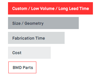
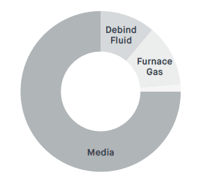
Cost estimates are essential for selecting parts for fabrication on the Studio System.
Upload your design file to Fabricate™ to view estimates for media costs (metal and ceramic) and estimated print, debind, and sintering times. Depending on how your organization calculates ROI, other costs like equipment, energy, service, and consumables may be important to consider.
-
Printing with Infill
The Role of Infill
Like parts printed using Fused Filament Fabrication (FFF), all parts printed with the Studio System contain infill. Infill describes the internal lattice structure printed throughout the part, enclosed by the solid walls that make up the shell of the part—creating what is called closed-cell infill.
The ability to lightweight parts with infill is a key advantage of Additive Manufacturing (AM). Using subtractive processes, you must redesign the part’s exterior or select a lighter-weight material to reduce the overall part weight. The top and bottom layers are printed solid (without infill), while the middle layers are printed with solid outer walls and the triangular infill pattern making up the interior structure.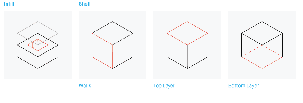
The Anatomy of a Studio System™ Part Infill & Fabrication Time
Part Geometry: Printing with infill reduces fabrication time, material cost, and part mass. Using infill reduces the amount of material and time required to print a part. It also reduces the debind and sinter cycle times, which depend on the cross-sectional thickness (wall thickness + lines of infill to the center of the part).
A solid part will take much longer to debind and sinter, or it might not fully debind, leading to serious defects like cracking or blistering.Example Part Example Part w/ Infill Example Part w/o Infill Savings Due to Infill Print Time (Hours) 7 11 36% Debind Time (Hours) 19 50 62% Total Fabrication (Hours) 67 100 33% Material (g) 170 280 40% Cost of Material $20 $33 40% Final Part Mass (g) 118 220 40% Infill & Part Strength
In combination with the outside shell, infill-based structures feature excellent rigidity at minimal weight. The shape of the infill geometry significantly impacts the effective modulus and the degree of anisotropy of structural properties. The Studio Printer prints with triangular infill, which offers several benefits over hexagonal or square infill geometries. Triangular infill results in a constant elastic modulus in the X-Y plane, ranging from 18-28% of the solid material’s elastic modulus. -
Strategies For Reducing Debind Time
During the debinding process, the part is fully immersed in debind fluid. The debind fluid is a solvent that dissolves the wax portion of the binder to create an open-pore structure in the part, allowing the remainder of the polymer binder to escape during sintering. The debind fluid surrounding the part must diffuse through the printed material until it reaches the center of the part. The distance that the fluid travels from the outer wall to the part center is known as the cross-sectional thickness. Fabricate uses the cross-sectional thickness to calculate debind time.
The wall thickness of the part impacts debind time. The cross-section reveals the wall lines (the compound path created by the two perimeter circles) and the lines of triangular closed-cell infill. Debind fluid flows freely between the voids created by the infill but dissolves slowly through the solid material of the wall lines and each infill line. Increasing wall line count leads to an increase in the length of the debind cycle.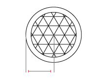
Cross-sectional Thickness The cross-sectional thickness equals the wall thickness plus the lines of infill to the center of the part.
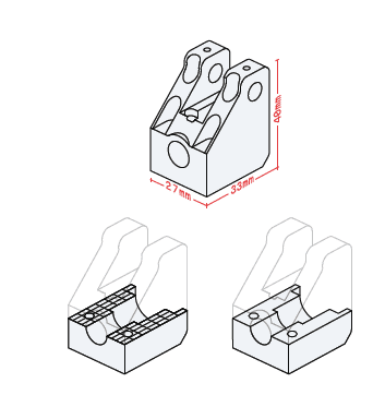
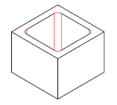
❖TIP ONE: [using CAD]: Reduce the cross-sectional thickness to shorten the debind time. Identify opportunities to modify your part design to reduce the cross-sectional thickness. One approach is to remove or ‘core’ thick sections of the part (similarly, you can add large indentations to thick sections of the part). For the example part, a cylindrical core has been removed. Now debind fluid can enter the part through the outer and inner walls. The distance to the center of the thick region of the part is, very noticeably, much smaller.
❖ Coring Example: Mold Insert
Coring the mold insert reduced the debind time by 3.5X and 14X, depending on the design approach.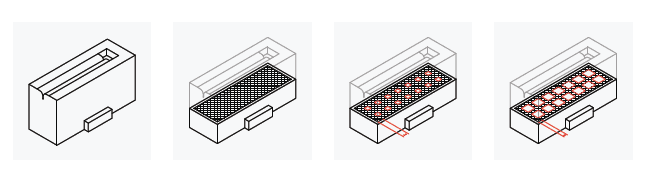
❖TIP ONE: Reduce the cross-sectional thickness to shorten the debind time. For the example part below, a cylindrical core has been removed.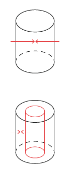
❖TIP TWO [Using Fabricate™]: Fabricate’s default setting for wall thickness, top layer, and bottom layer balance part strength and debind time. Increasing wall line count, top layer, and bottom layer in Fabricate’s advanced settings can increase part strength but will lead to longer debind times.
-
Optimize Print Orientation
How you orient your part during printing has implications for support material usage, surface quality, and fabrication time. When orienting your part, consider the following:
- Minimize support volume
- Minimize support volume to save print time and material. Avoid large overhanging portions of your part that rest on support structures.
- Avoid high centers of gravity
- Avoid orientations that elevate the part’s center
of gravity. - Avoid critical surfaces in contact with supports Surfaces in contact with support structures will have rougher surface quality. It is best to avoid having critical surfaces contact support structures.
-
Fillet Sharp Inside Edges
Sharp edges can concentrate stress in the part and increase the risk of cracking during sintering. Whenever possible, add a fillet to sharp interior edges.
-
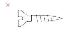
Avoid Printing Hardware
There are few instances when printing metal hardware will be less expensive than purchasing it off-the-shelf. Be strategic and consider the cost and benefit of printing parts—hardware rarely makes sense to print.
-
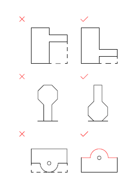
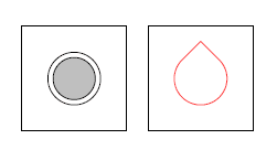
Holes
Supports may be necessary for horizontal holes of specific diameters, but Fabricate automatically generates supports. Users can avoid using support structures for horizontal holes by redesigning the circular hole into a teardrop shape, which utilizes a self-supporting angle. The self-supporting angle eliminates the need for supports.
-
Printed Threads
Many 3D printing companies, including those selling laser powder-bed fusion systems, recommend printing holes and then tapping threads. For the Studio System, tapped threads are recommended for threads from M3 to M9. In these cases, increase the wall line count to 5-7 lines (3 lines is the default setting) to ensure adequate material for cutting threads. Printing and chasing for M10 and larger threads will produce the best results.
Thread Size Method <M10 Print hole, tap threads ≥ M10 Print threads, chase threads 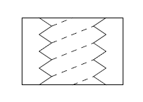
-
Cup-shaped Parts
During the debinding process, the entire part is immersed in debind fluid.
Once the debinding is complete, the fluid is drained from the tank and distilled for re-use in the next run. If the part being debound has a “cup” shape, that feature will hold debind fluid and prevent the part from completely drying.
Simple modifications can be made to parts to ensure that all the debind fluid drains from the part being debound. Adding small drainage holes (as small as 1mm) to your part design will allow the fluid to drain.
Alternatively, part orientation can also be adjusted. Keep in mind that part should have the same orientation for printing, debinding, and sintering so changing the part orientation for debinding means changing the orientation for printing and sintering as well. It is recommended that users orient parts to optimize full process success.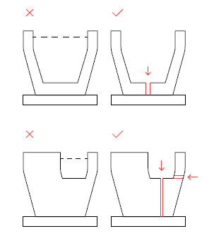
-
Clearances
Printed-in-places assemblies
For components of a moving assembly, clearance of 0.3mm (0.012in) is recommended between components.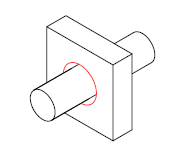
Close fit
For components to mate after sintering, a larger clearance of 0.3mm to 0.6mm (0.012-0.024in) is recommended.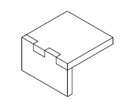
-
Supports
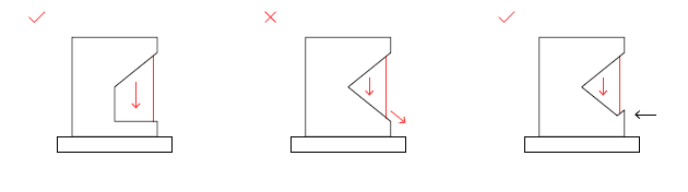
The interface layer plays an important role in the BMD part fabrication process. During the furnace cycle, the interface layer becomes a powder that physically keeps the part from sintering to the support structures. This enables Separable Supports™ and the significant benefit of allowing users
to remove support structures by hand. However, for some geometries, the fact that support structures are not strongly attached to parts during the sintering process may mean that parts can shift or separate from supports during the sintering process.One specific example is a feature that sits at an angle atop a support structure but does not meet the default angle requirement (40°) for generating overhang supports. In example one (shown below), the feature without overhang supports will slide down toward the object’s base during the sintering process. To prevent the part from shifting or sliding, the Fabricate angle setting for support overhang generation has been manually modified to a lower angle (below 40°), causing supports to build for the overhanging features. This support structure will now “cradle” the part during sintering, preventing the part from shifting.
❖TIP ONE: Adjust the support angle to a lower angle, which will cause supports to build to the overhang features. The support structure will now “cradle” the part during sintering, preventing the part from shifting.
Modify support angle criteria to generate support for overhang It is also possible for support structures to shift during the sintering process if they are built atop an angled surface. While a support structure with a flat base will remain stable during sintering process, one built on an angled base may want to slide away from the part. To avoid this situation, the original part geometry should be modified. Adding a small lip or bump to the part where it contacts the bottom of the support structure will prevent the support structure from shifting during sintering.
❖TIP TWO: If you notice that Fabricate is generating supports with an angled base, consider modifying your design in CAD. Add a small lip or bump to the part where it contacts the bottom of the support structure.
Modify part geometry to secure support structure -
Aspect Ratio
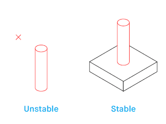
The most slender vertical cylinder that can be printed, debound, and sintered has an aspect ratio of 8:1 (height : diameter). It is attached to a larger base – rather than a free-standing feature. If the slender cylinder is a free-standing feature and sits directly on the raft instead of being attached to a part, the cylinder will be less stable. This is because the cylinder will sit directly on the ceramic interface layer, which turns to a powder during the sintering process, creating an unstable base for the cylinder to sit on. For free-standing cylinders, the aspect ratio of the feature should be reduced by 40% to about 5:1.
-
Centre of Gravity
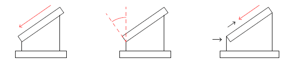
Most features and parts are not perfect vertical cylinders. In these cases, it is important to note where the center of gravity of the feature is located. Features are most stable when the center of mass is sitting above the base. A less stable feature is one where the center of mass is not vertically supported. An example is a tall pillar on a slight angle (shown left). During sintering, the feature will want to fall over or slump when the material is weak.
There are a few options for addressing features whose center of mass does not sit above the base of the features. Through modifications to the original geometry, stable features can be created. The first solution is to attach the overhanging feature to a larger, more stable part. In this instance, the center of mass has now been moved to a location above the base of the feature. Another solution is to add support trussing, pillars, or other features. When adding supporting features, attach them to the original feature in such a way that will support the part during sintering. It is good practice to ensure that the center of mass is located within the bounds of the base of the original feature and support features.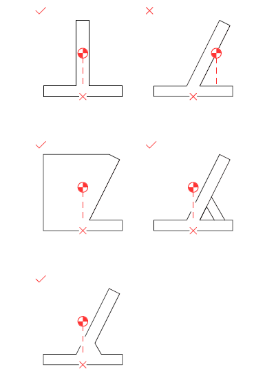
- Company
- Products
- Manufacturing Services
- Resources
- Why Silicone 3D Printing?
- Fuse 1 | SLS Design Guidelines
- Technical Support, Repairs for 3D Printing, CNC Milling, 3D Scanning
- Terms and Conditions – Annual Maintenance Contract Proto3000
- Billable Technical Support & Repair Services
- Proto3000 Webinar Series
Skip to content

Bound Metal Deposition 3D Printing Design Guidelines
Considerations & best practices for 3D printing with Desktop Metal®’s Studio System
3D Printing Services
- Additive Manufacturing Services
- 3D Printing Technologies
- Materials
- Finishing and Assembly
- Digital Light Processing (DLP) Design Guidelines
- MJF Design Guidelines
- PolyJet 3D Printing Design Guidelines
- FDM Design Guidelines
- SLA 3D Printing Design Guidelines
- SLS Design Guidelines
- BMD Design Guidelines
- Metal Binder Jetting Design Guidelines
- DMLS Design Guidelines