-
Introduction
This step-by-step guides was designed as a resource to assist in creating hydroforming and rubber pad pressing tools with Fused Deposition Modeling (FDM) 3D printing technology. If you have complex requirements or have any further questions about using FDM 3D printing technology for sheet metal forming and tooling applications, be sure to speak with one of our experts. If you are looking to have higher volumes of parts produced with 3D printing technology, be sure to use our 3D printing services or click here for an instant quote.
For simple bending on a press brake, to automated fine blanking, stamping, or progressive die – there are endless ways to form, fabricate and manufacture sheet metal parts. The two methods of this are hydroforming and rubber pad forming, which are both commonly used for the following:
Aerospace
Military
Commercial
AutomotiveTheir methods of operation are in stark contrast to the sharp, rapid-fire strike of a metal die on sheet metal stock. By using a slow buildup of high-pressure VS. impact force, hydroforming and rubber pad presses have the ability to produce complex part configurations.
Although counter-intuitive, the high-pressure forming methods create an opportunity to make sheet metal parts from lightweight, plastic tools that were made from fused deposition modeling (FDM). When comparing to machined metal tools, the FDM 3D printing approach is commonly quicker, less expensive, and requires much less labour. These attributes combine together to make FDM 3D printing an interesting alternative for repair and refurbishment work. (As found with aging aircraft/products with a high probability of design revisions).
-
Overview
Application
Fused Deposition Modeling 3D printing is an alternative tool-making method for sheet metal forming with hydroforming or rubber pad press processes. FDM holds the possibility to manufacture tools including:
Form Blocks
Intensifiers
Drill Templates
Trim toolsFDM is best fit when:
Forming pressures – hydroforming is up to 10,000 psi (69 MPa). Keep in mind that the maximum forming pressures solely depend on the material that’s being used in the FDM tool. FDM is also best when rubber pad press is up to 1,000 ton (907 metric ton). Note that the draw depth shouldn’t go over 3.0 in. (76 mm)
Sheet metal specification – tests show that aluminum, stainless steel, and titanium that have a sheet thickness up to 0.090 in. (2.29 mm) are compatible with FDM tooling. Other untested materials could also qualify.
Low Volume Forming Runs – FDM tools have exceeded 400 cycles without failure. Howveer, that tool life depends on the FDM material which is being used. Sheet metal material, bend radii, part configuration, and forming pressure. Ideal applications include low-volume production, repair and refurbishment of legacy products, custom products, and prototype development.
Part size – works best when FDM tool does not exceed 16 in. x 14 in. x 16 in. (406 mm x 356 mm x 406 mm). Yet, largertools are feasible, especially if they are larger in only one dimension.
Part design – gains are best when sheet metal component is complex and feature-laden
-
Sheet Stock Specifications
Materials Formed On FDM Tools
Ongoing evaluation programs showcase the materials listed in the table below are suitable when forming on FDM tools. For softer materials, sheet thicknesses of up to 0.090 in. (2.29 mm) have been processed. the material list is not exhaustive and exclusion doesn’t imply incompatability.
Material Grade Thickness Aluminum 2024-0 0.050-0.090 in. (1.27-2.29 mm) 2024-T3 0.050-0.080 in. (1.27-2.03 mm) 6061-0 0.016-0.080 in (.0.41-2.03 mm) 7075-0 0.040-0.090 in. (1.02-2.29 mm) Stainless Steel 4130 0.080 in. (2.03 mm) 420XF 0.040 in. (1.02 mm) 321 0.049 in. (1.24 mm) 347 0.002 in. (0.51 mm) Titanium Unspecified 0.40 in (1.02 mm) Inconel Exploratory -
Traditional Process Overview
The following are the steps in order to achieve the traditional metal forming process:
- Hydroforming
Fabricate form block
Place form block and sheet metal blank in chamber
Fill bladder with hydraulic fluid to raise pressure as high as 15,000 psi (105 MPa)
Raise punch (optional)
Sheet metal formed to shape of form block2. Rubber pad press:
Similar to above, although flexible pad replaces the hydraulic fluid, and pad presses down over tool to form sheet metal.
FDM Adjustments
To include FDM tooling within the metal forming process, adjustments, alterations and substitutions are made to the following steps
- Form Block
Adjustment is required (decreasing in most cases) - Forming Pressures
Limit forming pressures to 3,000-10,000 psi
(21 MPa-69 MPa) this is material dependent
In order to reduce pressure, add intensifier - Forming
Lubrication is necessary
Cycles per part may be reduced in certain instances. Inherent porosity of FDM form blocks bleed air that would otherwise be trapped.
-
Tool Design
In order for FDM tooling to be applied to the metal forming process, the form block, as well as intensifier designs require minor adjustments. If the user is making companion tooling like trim templates, no alterations are necessary.
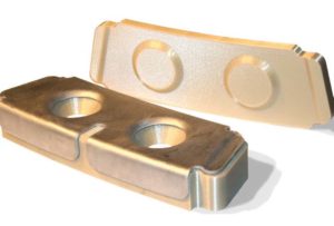
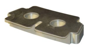
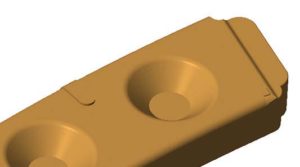
Form Block
Form Block
Use conventional tool design practices with slight adjustment to springback compensation. Under the forming pressures, a FDM tool could have a small amount of deflection that decreases or eliminates the amount of springback in the sheet metal component. In order to avoid overcompensation, its suggested to start with a tool design which has no compensation. Similarily to conventional tools, if a sample run shows that adjustment is required, FDM form block could be machined. Alternatively, the springback correction could be added to the CAD design before rebuilding the tool.
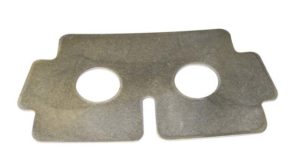
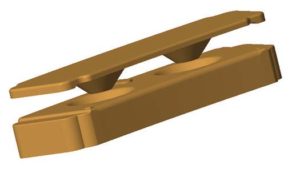
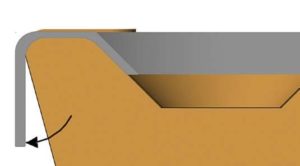
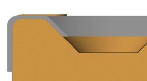
Intensifier
FDN intensifiers must be designed for use with a specific sheet metal thickness. If gaps exist between the intensifier, sheet metal blank and form block, the forming pressures may cause the intensifier to crack. Design the intensifier with a minimum material thickness of 0.38 in (9.7 mm). Furthermore, offset the intensifier from the form block simply by the thickness of the sheet metal blank. Then you can extend any surfaces which aren’t in contact with the blank
Export the STL File
After the tool design, export all CAD model as STL file. Be sure that settings (chord height, chord deviation, angle control, ect) will produce fine mesh (small facets). This reduces the post-processing effors and preserve accuracy.
-
File Preparation
Import the STL files into Insight and then use the standard workflow for job processing.
The key alteration when building an FDM form block is to make it a dense part with many surface contours (toolpaths around the perimeter of a curve). Density is achieved with negative air gaps between adjacent contours and between adjoining rasters and contours. Intensifiers, templates, and guides can be built with default parameters for a solif fill style.
Modeler > Setup
When using ULTEM 9085, ensure that System mode is set to Normal. This paremeter is available from the Modeler>Setup window after selection of ULTEM 9085 as the model material. Some system have the default as Thin Wall, a style which may cause the form block to lift from the build sheet.Orient STL
Consider total process time, feature strength under a compressive load, and smoothness when orienting from the form block. Usually this leads to an oritentation that is the same as the tool when its placed in the forming press.Create Custom Group
In order for the block to gain a dense fuull with thick contours, create a custom group and apply it to all layers.Create “Metal forming CG.”
Select Toolpaths > Custom groups > New and name thegroup “Metal forming CG.” Select the checkmark to save.Adjust toolpath parameters – select modify and change the following:
Contour style = contours to depth
Depth of contour = 3, meaning this adjustment creates thicker perimeters around each figure. Furhtermore, adjust the air gaps to increase the internal density and strength of the form block. While on the monitor screen, adjust the air gaps for contour and contour = -0.001 in. (-0.03 mm), and contours and rasters = -0.0005 in. (0.013 mm). Be aware that if overfilling takes place around the edges, adjust contours and rasters air gap to -0.0005 in. (0.013 mm). This is more likely to occur if default raster widths have been set to larger values.Apply “Metal forming CG”
Select all curves and layers, then select “add”
Toolpath Adjustments (optional)
Toolpath adjustments are used in order to alter, refine, or build from “metal forming CG”
Adjust custom group for speed. Open up “material forming CG” custom group, then proceed to “modify”. Increase the v alue for “raster width”. The value has the ability to be adjusted to user discretion, however when using at T19 tip, it could possibly be safely increased to 0.024 in. – 0.028 in. (0.61 – 0.71 mm).
Add custom group for surface finish. This custom group was directed at visible, upfacing surfaces – downfacing if the tool is inverted. These surfaces contact the sheet metal blank. A smaller raster is used to improve the smoothness of forming surfaces.
Next, proceed to toolpaths > custom groups > new and click on the template icon. From the template group dropdown menu, select “metal forming CG”. Click off the checkmark in order to accept. Then, change the Group name to “Forming surfaces”. These adjustments are required for the following settings:
Raster width = 0.017 in. (0.43 mm)
Adjacent raster air gap = -0.001 in. (-0.03 mm)
Display colour = Cyan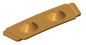

-
Material Suggestions
There are three FDM materials that have been assessed for form block fabrication. The key selection criterion is forming pressure.
Options
ABS-M30: <3,000 psi (21 MPa)
Polycarbonate (PC): < 6,000 psi (41 MPa)
ULTEM 9085: < 10,000 psi (69 MPa)ABS-M30 is an option for low-pressure applications. Tool life will more than likely be shorter for ABS-M30 form blocks, so 100+ cycles is a necessary expectation, and 400+ is achievable with sheet materials like 2024-0 aluminum.
However, ULTEM 9085 should be saved for high-pressure forming.
Polycarbonate, otherwise known as PC, is the ideal material when using all other applications. Mid-range pressures can resist durable form blocks that have been produced from the mechanical properties.
Tool Life
FDM materials that produced form blocks will stabalize within ten cycles. Within the first couple cycles, the forming pressure could cause minor compression of the tool. In most instances, the most noticeable effect is slight rounding of sharp corners.
The upper threshold of tool life has yet to be determined for these FDM materials. No programs, or research projects have proven FDM tool to fail, when the proceeding design and operation guidelines have obviously been followed. But due to low quantities necessary within the programs, no data or information on any tool more than 400 cycles has lived.
-
Post Processing
After the FDM building process has been finished, remove the support material from the form block. No other post processing is required.
Venting
Venting that may be required in some form blocks is unnecessary in any tool that is made with FDM. The FDM form block has a antural porosity where air is allowed, which usually would be trapped to pass through the tool.
Surface Finishing (Optional)
If forming thin sheets (<0.040 in./1.0 mm) if sift metals, like aluminum, the raster pattern of the FDM form block could transfer to the sheet metal part. Noticeable patterns are likely if the tool uses large slice heights and wide rasters. If this takes place and if a texture is not as appealing as planned, smooth all forming surfaces.
Option 1 – Sanding
Smooth all surfaces that come into contact with the metal blank by using 120- to 320- grit sandpaper. Since the outermost point of a surface is created at the nominal dimension, material removal could have a possible affect on accuracy. To counter this, either minimize the amount of material removal or offset the CAD surfaces before exporting the STL file. The form block could also be filled and sanded.Option 2 – Filling and Sanding
Start off by filling all depressions and valleys with a body filler (ensure to follow manufacturers instructions). There are numerous of suitable fillers, two materials which work well and are relatively common in a metal forming shop are:
1. PTM&W PT1158 – two aprt epoxy surface coat
2. PTM&W Polyfill RT – two part polyesterSand all surfaces with 120- to 320- grit sandpaper after the filler has dried. If stripe patterns appear, alternate between the colour of the filler and the colour of the FDM material, then shift to a finer grit paper for light material removal with smoother surfaces.
-
Metal Forming
When working with forming press operations, there are no required alteration or adjustments. FDM form blocks and instensifiers need no special handling instructions.The only caution is to confirm that the forming pressures are compatible with FDM material used to create the tool.
Lubrication
Natural lubricity is offered with thermoplastic FDM materials so the form block doesn’t require any lubrication between cycles. If lubrication is warranted, use a mild water-based detergent. it’s crucial to NOT lubricate an FDM tool with a petroleum-based product.
Cleaning
If the tool requires cleaning, wash the form block with a mild, water-based detergent, like Dawn or Simple Green. DON’T clean with petroleum or alcohol-based degreasers or solvents.
-
Tools and Supplies
Beyond the items used in a routine metal forming operation, there is nothing required.
Optional Items
Fillers (PTM&W Polyfill RT)
Sandpaper
Water-based detergents. -
Recap
Critical Success Factors consist of FDM tools:
Match FDM material to forming pressures
Do not exceed those recommended for each material
Intensifiers are required for higher pressures
Increase contour thickness and decrease air gaps
- Company
- Products
- Manufacturing Services
- Resources
- Why Silicone 3D Printing?
- Fuse 1 | SLS Design Guidelines
- Technical Support, Repairs for 3D Printing, CNC Milling, 3D Scanning
- Terms and Conditions – Annual Maintenance Contract Proto3000
- Billable Technical Support & Repair Services
- Proto3000 Webinar Series
Skip to content
