-
General Considerations
Designing Shop System™ parts
Shrinkage
Parts produced with the Shop System™ shrink during the sintering process due to the evaporation of the binder from the part and consolidation of metal particles, as well as the elimination of any pores left from the binder. Depending on the specific material, shrinkage may be as high as 25%. Desktop Metal® Fabricate® MFG automatically calculates shrinkage, eliminating your need to address it.Setters
During the sintering process, parts are in a malleable form and require sintering setters which support the parts from below to prevent sagging and other deformations. When designing the part, avoid large overhangs (>10-15mm length) that cannot be supported with a setter. -
Quick Reference
Feature Recommendation The consequence of not following recommendations Part Size - 150 x 100 x 50 mm
- (6 x 4 x 2 in)
- Part is larger than the recommended maximum size.
- During sinter, the part will shrink large physical distances and be subject to frictional and/or compression forces.
- May result in drag marks and cracks.
Wall Thickness - Maximum wall thickness = 25 mm
- Minimum supported wall thickness = 0.75 mm
- Wall thickness is larger than the recommended maximum.
- Large walls will be unable to release binder thoroughly, and excess binder may remain in the part.
- During sinter, the binder that cannot leave part may cause cracks.
- Wall thickness is smaller than the recommended minimum.
- Small walls will be extremely fragile in depowder.
- It can lead to breaks or failures from cracking.
Wall Aspect Ratio - 8:1 for wall widths greater than 1 mm
- 4:1 for wall widths under 1 mm
- Wall aspect ratio higher than the recommended maximum.
- During sinter, tall walls will be unstable.
- It can lead to distortion and sagging.
Minimum Hole Width .075 mm - Hole width smaller than recommended minimum.
- During depowder, powder removal of small holes will be difficult.
- It can lead to incorrect geometry.
Hole Aspect Ratio - 8:1 for holes of diameter greater than 2mm
- 4:1 for holes of diameter less than 2mm
- The hole aspect ratio is higher than the recommended maximum.
- During depowder, powder removal of holes will be difficult.
- It can lead to incorrect geometry
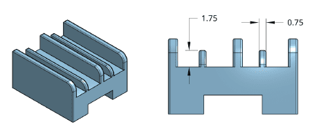
Pillar Width - Minimum pillar width = 0.75 mm
- Maximum pillar width = 25 mm
- Pillar width smaller than recommended minimum.
- Small pillars will be extremely fragile in depowder.
- Can lead to brown part breaks.
- Larger pillars will be unable to debind thoroughly, and excess binder may remain in the part.
- During sinter, the binder will be unable to leave part, leading to cracking.
Pillar Aspect Ratio The aspect ratio should not exceed 8:1. For example, the pillar’s height should be less than eight times (8x) its width. - Pillar aspect ratio higher than the recommended maximum.
- During sinter, tall pillars will be unstable.
- It can lead to distortion and sagging.
Overhang - Overhang length longer than the recommended maximum.
- During sinter, large over-hangs will be unsupported in the sintering temperature.
-
Optimizing design of Shop System™ parts
The most important design considerations for optimizing printing with the Shop Sys-tem™ are for:
- Part size
- Wall thickness
- Minimum wall thickness
- Aspect ratios
-
Part Size
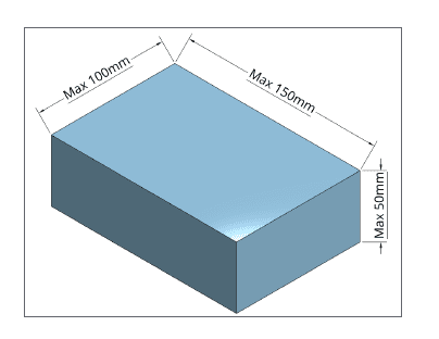
For best results in printing and sintering, limit the part size to:
150 x 100 x 50 mm (X, Y, Z)
Due to the print process, this is the “as modeled size,” not the size after scaling. Adhering to the recommended part dimensions ensures the scaled part stays within the print parameters of the printer and sinters without cracking.
-
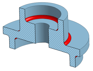
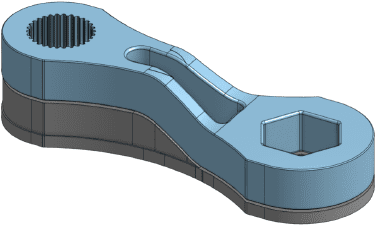
Maximum wall thickness
The upper limit of the wall thickness is determined by the ability of binder to diffuse through the wall during the sintering process.
For successful removal of binder during the debind step of sinter, Desktop Metal® recommends:- maximum wall thickness of 25 mm
- not to exceed 25 mm in more than two axes
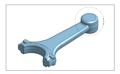
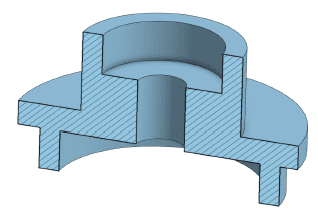
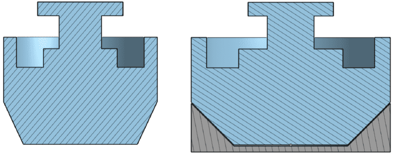
Detail View A: Length and width (X and Y axis) exceed 25mm. The thickness on most of the part is <25mm. Thickness in Detail View A is >25mm in all three axes. 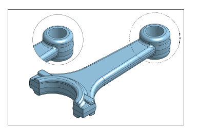
Detail View B: Shows material removed in Detail View A, allowing overall linear dimension to exceed 25mm. -
Minimum Wall Thickness
Wall thickness under 0.75 mm results in insufficient strength in the brown part. Thicknesses between 0.75 mm and 2 mm may still be fragile during the depowdering stage, so be careful when handling parts.
-
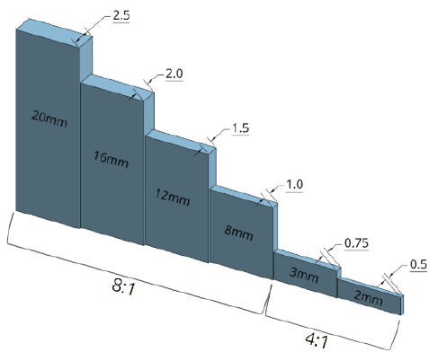
Aspect ratios
Aspect ratios drive allowable feature size. Specifically, the size or width of the feature limits the maximum achievable wall height, slot depth, and hole depth.
Pillar and wall height to width
The width of the wall or pillar limits its height. The aspect ratio for the wall is defined as the ratio of the height to widthWalls between 0.75 and 2 mm in thickness will be very fragile, and care should be taken during depowder. Aspect ratio requirements are split into two categories depending on wall thickness:
- Walls widths <1mm not to exceed 4:1
- Walls widths >1mm not to exceed 8:1
-
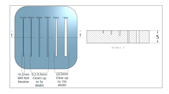
Slot Depth to Width
The width of a slot must be ≥0.5 mm to fully depowder and be visible in the sintered part. Slots with widths >0.2 mm and <0.5 mm will be visible on the surface up the part but may not achieve the designed depth on the part’s surface. For slots that project through an entire surface, a depth to width ratio of 8:1 should be maintained to remove powder from slots during depowdering without the use of special tools.
-
Hole Depth to Diameter
The diameter of a hole must be ≥0.75mm to resolve and be visible in the sintered part.
The hole aspect ratio cannot be >8:1, meaning the depth of the hole cannot be greater than 8x its diameter.
If the design does not meet this standard, problems may occur during depowdering because the powder is inaccessible in long, thin channels. For holes of smaller diameters (- 2mm or less), the aspect ratio is lowered to 4:1, meaning the depth of the hole cannot be greater than 4x its diameter.
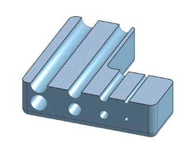
Hole >2mm in diameter, aspect ratio exceeds 8:1: Will resolve and depowder successfully.
Hole 2.0mm in diameter, aspect ratio equal to 8:1: Will resolve and depowder successfully.
Hole <2.0mm in diameter, aspect ratio equal to 4:1: Will resolve and depowder successfully.
Hole <0.75mm in diameter, aspect ratio less than 4:1: Will not resolve and will not depowder successfully. -
Internal Channels
Internal channels should meet the aspect ratio design guidelines for holes; however, sharp turns must be avoided. Use tools to aid depowdering.
Depowdering will not be possible in this part due to the sharp turn in the channel, making it inaccessible.
-
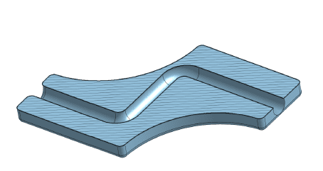
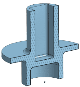
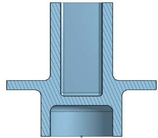
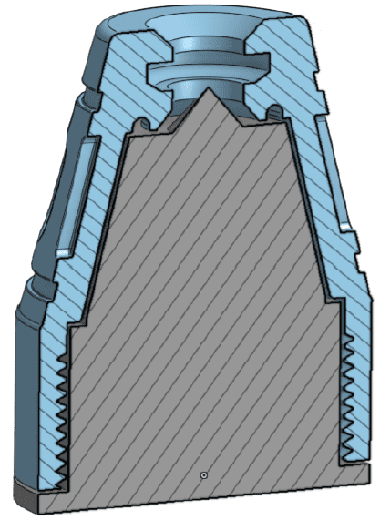
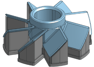
Tubes
Standalone tubes are some of the most challenging features to process during depowdering. Tubes have long aspect ratios and small internal diameters.
Tube thicknesses should meet the aspect ratio guidelines for wall height to the thickness and should avoid sharp turns.
Features should be added to tube support, aiding the ability to depowder and sinter them.
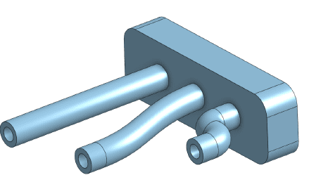
Sharp turns in channels inhibit the ability to depowder. Long unsupported channels are likely to slump during sinter.
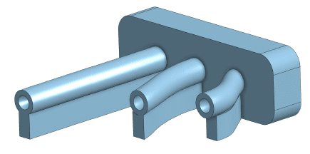
Gradual changes in tube patch direction facilitate depowdering. Supporting geometry beneath tubes prevents slumping during sinter.
-
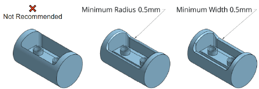
Removing Knife Edges
Avoid sharp edges and points with acute angles <70 degrees. Terminate sharp edges with a flat or radius of at least 0.5mm to avoid chipping and breaking during the depowdering process.
-
Designing Internal Corners
For internal corners, use a fillet with a radius approximate to the thickness of connecting walls and >1mm. Filleted corners enhance the brown part’s strength and help prevent distortion and cracking during sintering.
-
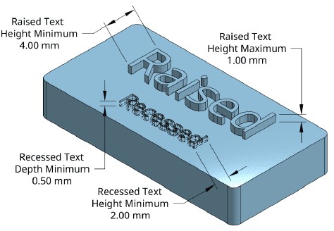
Designing Text Features
Text features have minimum and maximum specifications to prevent the breakage of fragile features. Raised and recessed text have different specifications.
Recommended minimum/ maximum dimensions for text features
For recessed text:
- Minimum 2mm in text height (~6 point font size)
- Minimum 0.50 mm in recess depth
For raised text:
- Minimum 4mm in text height (~12-point font size)
- Maximum 1mm in raised height
Use caution when depowdering text, especially raised text. Small features, like the small dot on an “i” or “j” are effectively tall thin pillars that could exceed the design guide aspect ratio. Avoid recessed text that passes all the way through part geometry. This may leave free-floating entities such as the centers of an o and d. Favor simple sans serif fonts. Prevalence of thin sections cause unnecessary feature fragility. In general, recessed text and sans serif fonts provide the best results.
-
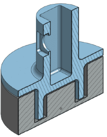
Part Features Requiring Sintering Setters
While supports are unnecessary for shape retention during printing, setters are critical during sintering when the material approaches its melting point. Powdered metal parts are sintered at high temperatures and have very little strength. The forces of gravity are enough to distort parts unless they are properly supported. Parts that do not have flat bottom-facing surfaces require part-specific sintering setters. Primitive setters can be manufactured out of ceramic or form-fitting setters can be printed in tandem with parts. Printed or live setters are of the same material as parts and require an anti-sintering agent to be separable after sintering.
Bridges and Overhangs
Bridged features greater than 20mm and overhangs greater than 7.5mm require the use of a sintering setter.
Angles
Overhanging features which deviate more than 30 degrees from vertical require a sintering setter.
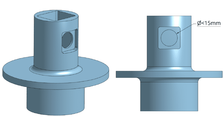
Horizontal Holes
Holes in the horizontal axis of the part with diameters greater than 15mm require a sintering setter.
-
Other examples of sintering setters
- Company
- Products
- Manufacturing Services
- Resources
- Why Silicone 3D Printing?
- Fuse 1 | SLS Design Guidelines
- Technical Support, Repairs for 3D Printing, CNC Milling, 3D Scanning
- Terms and Conditions – Annual Maintenance Contract Proto3000
- Billable Technical Support & Repair Services
- Proto3000 Webinar Series
Skip to content

Metal Binder Jetting 3D Printing Design Guidelines
Considerations & design best practices for 3D printing with Desktop Metal®’s Shop System™
3D Printing Services
- Additive Manufacturing Services
- 3D Printing Technologies
- Finishing and Assembly
- Digital Light Processing (DLP) Design Guidelines
- MJF Design Guidelines
- PolyJet 3D Printing Design Guidelines
- FDM Design Guidelines
- SLA 3D Printing Design Guidelines
- SLS Design Guidelines
- BMD Design Guidelines
- Metal Binder Jetting Design Guidelines
- DMLS Design Guidelines