-
Introduction to 3D Printing and Molding
This step-by-step guides was designed as a resource to assist in creating silicone parts with 3D printed molds. If you have complex requirements or have any further questions about using PolyJet 3D printing technology for silicone molding applications, be sure to speak with one of our experts. If you are looking to have higher volumes of parts produced with 3D printing technology, be sure to use our 3D printing services or click here for an instant quote.
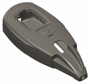
Liquid silicone rubber (LSR) is a commonly used material due to its versatility and unique properties. It’s non-reactive, stable, and resistant to extreme environments and temperatures. Mass production of LSR parts that uses injection molding machines that meter, mix and inject LSR into a heated mold. Because of cost and time that comes along with this process, low-volume production and prototyping is often done with manual casting methods that use molds made of modeling board, RTV rubber or soft metal.
Although they are easier, faster, and cheaper to produce, prototype molds come with their own difficulties. Producing LSR parts with RTV molds is a milti-stage process that needs lots of time and labour to make the patterns and molds. Care is also needed to ensure the soft rubber RTV mold doesn’t deform or stick to LSR parts. Machined molds master these difficulties, however, they can be more costly, time-consuming, and labour intensive than RTV molds. Furthermore, machining could have limitations with respect to the complexity of a certain part’s design.
PolyJet™ technology offers an alternative method for producing LSR molds with dramatic time and cost savings. By using PolyJet 3D printed molds, LSR parts can be made in as few as one to two days. After designing the mold in CAD, it’s then printed. It’s typically printed overnight, without an operator present or added time for complex designs. PolyJet molds maintain fine details and deliver smooth surface finishes. PolyJet molds are ready to construct silicone rubber parts after only a couple of minutes of labor (for cleaning and assembly).
Application Compatibility Technology Idea Design Production FDM 2 2 3 PolyJet N/A 4 5 -
Process Overview
The process for producing LSR parts s similar to using machined tooling. PolyJet mold is simpy replaced for the machined tool. Ensure to adjust curing cycle parameters.
MOLD Design Mold Design Cores (optional) Print Mold CASTING Assemble Mold Mix and Inject LSR Cure LSR Eject Part


-
Create Mold
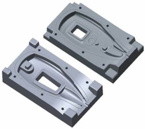
Construct a rectangular block that is about 20 mm (0.75 in.) larger than the part on all sides. Then, center the CAD model of the part in the block and use a Boolean subtraction, otherwise known as an operation used in CAD modeling, to remove it from the block. The cavity is then created within the mold.
In order to complete the mold design, make a parting line and add locators, gate, vents and clamping features. When and if necessary, design cores that are used to create interior features.
Create parting line
Split the block along the desired parting line for the mold
Add locators
Add locators at the four corners of one side of the mold. The halves will become perfectly aligned once merging has been completed to the opposite side’s matching location holes. Next, add locators that will be male stand offs, to one side of the mold and make them large enough to positively engage with the opposite side. A width and height of 13 mm (0.5 in.) for smaller molds should created for them. You may increase their size to >200 mm (8in) for molds which are larger. It is also necessary to taper the stand-offs with a 0.5° to 3.0° angle to allow them to seat in the receiving holes. On the opposite side of the mold, make tapered receiving holes that use the same locations and dimensions as those for the stand-offs. Make the holes 0.12 mm (0.005 in.) larger and deeper than the stand-offs in order to ensure flush seating of the mold halves.
Add injection ports and vents
Determine where the liquid silicone rubber will be injected on the mold. It’s recommended to select a location in the least visible area of the part. Keep in mind, larger silicone parts or short pot-life silicone’s could need multiple injection ports or vents.
In the desired location, add a hole through the mold half to create the injection port. The hole’s diameter will be controlled by the nozzle size of the injector, but usually, it will have a 9 – 11 mm (0.4 – 0.5 in) diameter at the opposite end of the part cavity.
When producing LSR prototype parts, it’s good to consider adding more vents to the mold. Witness marks which remain after vent removal could be acceptable during the design evaluation. If this deems to be correct, having multiple vents will make it easier to fill the mold cavity with LSR. It will also avoid incomplete filling of the mold.
Add clamping holes
Use bolts in order to keep the mold halves from splitting up during the injection of silicone rubber. Add holes for the bolts to pass through around the periphery of the core and cavity. All holes should have a diameter 0.13 mm (0.005 in) larger than the bolts.
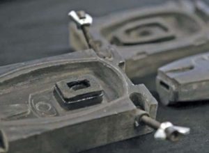
The mold also has the option to be designed with a rapid release system that uses built-in fastening features. Integrated pivots hold bolts that are rotated into a locking position. This clamps both mold halves together.
First off, design the pivot by bringing two cylinders together in a “T” formation. The legs providing rotation are solid cylinders. The other leg is threaded to match the bolt that will later be inserted.
On the four corners of one side of the tool, features should be added that hold the pivots and allow them to rotate 90°. These features will have a hole which intersects a channel that has a 70° to 90° bend. Both the diameter of the channel and hole should be 0.30 to 0.35 mm (0.012 to 0.14 in) larger than the pivot. Complete the mold half’s design by placing the pivot geometry in the four features. On the other mold half, add four open-ended slots which are 0.5 mm (0.02 in) larger than the bolts that are going to be inserted into the pivots.
Add flash prevention rib (optional)
To reduce flash on the LSR part, add a small rib around the periphery of the part cavity on one side of the mold. To avoid breakage during molding, ensure the rib is at least 3 mm (0.13 in) tall and 3 mm (0.13 in) wide. Create a receiving channel in the opposite side of the mold that has a depth and width that is 0.12 mm (0.005 in) larger than the rib.
Create Cores
For LSR parts with internal passages or hollow interiors, cores will always be necessary. Cores have the ability to be used to form openings through the part’s walls. Start off by making a CAD model which represents the interior portions of the silicone part. Next, extensions should be added to the model so that there is support on the core when it’s loaded into the mold.
Split the core for extraction (optional)
LSR tends to grip the core, and if a rigid silicone is used, it could possibly trap the core. In order to prevent these challenges, strategically separate the core into multiple pieces to allow extraction. Split the core for quality (optional). PolyJet molds and cores will perform best when the molding surfaces have a gloss finish which is only attainable if printed in an upward facing direction. Seeing as both the top and bottom of the core will be molding surfaces, a glossy finish on all surfaces will need the core to be separated.
Cut the core along a plane that is parallel to the XY plane of the PolyJet printer wen the core is oriented for printing. When splitting the core, use zero tolerance on the surface to ensure that the fit is tight
Add location features that align the halves together. On one half, posts with a 5° taper should be added. On the other half, tapered receiving holes of 0.1 mm (0.004 in) larger and deeper than the posts should be added.
Generate STL files
After the CAD design is finished, save the model as an STL file. Ensure all settings are adjusted, such as chord height, for the STL file so that small facets are created. This produces surfaces that need much less post-processing when preparing the pattern.
-
File Preparation
STL files should be imported into the Objet Studio™ software and then be prepared for 3D printing.
Orient STL files
Orient the mold and core components so the molding surfaces have a glossy finish, and are left with no support material contact. (Left click on Part > Transform > Rotate).
Select Surface Finish
In order to achieve a smooth, nearly mold-ready finish, all mold components should be printed using the Glossy finish (Left click > Glossy). The gloss finish assists in sealing the surface. Where as a matte finish will allow for some leaching of the LSR, inhibiting its cure, and cases faster degradation. This will result in a shorter mold life.
Set Printing Mode
Select High Quality when available for the printing mode to produce the smoothest surfaces, as well as minimize post processing.
-
Materials
Digital ABS™ is the preferred 3D printing material for LSR molding. It provides the longest tool life and is also best suited for molding silicone rubber. However, Vero™ materials (VeroBlue™, VeroGrey™, VeryWhite™ and VeroBlack™) are also suitable for this application. Though the mold life will be shorter compared to Digital ABS because the materials degrade quicker. Molds made with Vero materials often use a lower pre-heat and curing temperature.
-
Mold Preparation
After the PolyJet mold has been constructed, post-process it in order to remove support material and finihs the surfaces to the desired level of smoothness.
Remove Support Material
Scrape the support material from the mold halves using a putty knife or similar tool for the rectangular mold and core halves.
If cores weren’t split and have support materia on a molding surface, remove the support material with a waterjet. Furthermore, soak the cores in a 2% sodium hydroxide (NaOH) solution for two hours. Then, wash the cores thoroughly with water and let them dry.
Smooth Surfaces (Optional)
The surface smoothness of the PolyJet cavity will contribute to the aesthetic of the silicone part. It’s crucial to have all surfaces as smooth as what is required for the intended application.
Sand all surfaces if the cavities and cores to a smooth finish. Begin with a medium-grit wet/dry sandpaper (180- to 220- grit). Sand until the surfaces are clearly smooth. Use fine grit sandpaper (320- to 400-grit) to complete this sanding step.
After sanding the part, use water to remove all dust from the surface. Then let it dry.
Bond Core Halves (Optional)
Use an adhesive like cyanoacrylate, to the mating surfaces of two core halves. Mate the halves and hold/clamp until the adhesive has cured. Repeat for all the remaining core halves.
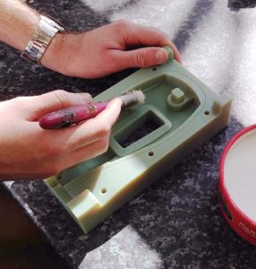
Seal Surfaces
Apply KantStk® (a mold sealant) to the mold cavity and all cores. Then, coat and buurnish the same surfaces with a carnauba mold release wax.
Assemble Quick Release Feature (Optional)
For molds with quick release features, ensure that pivots are rotating freely. Then, palce a wing nut on each bolt. Screw the bolts into the four pivots. Assemble the mold and then confirm that the clamping bolts have the ability to be rotated into position.
-
Part Molding
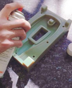
Assemble the Mold
Apply a light spray of silicone release to the mold cavity and cores, then pre-heat the mold at 70 °C (158 °F)*. Finally, have the cores placed in the cavity, mate, and mold halves and join with bolts. For Vero molds, pre-heat at 60°C (140°F).
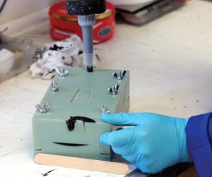
Mold Silicone Parts
Following metering and mixing the LSR material, degas it for about 20 minutes. Then, load the LSR in an injection tube and manually expel all of the air. Next, inject the LSR into the mold and allow the material to be cured for an hour and a half at 70°C (158°F).
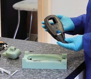
After curing, separate the mold, extract the part and extract the cores. If extraction is challenging, blow compressed air between the part and mold.
The final step is to trim flash, injection port and vent material from the LSR part. For Vero molds, cure at 60°C (140°F)
-
Key Process Considerations
Resolution Details:
Obstacle Resolution Material Selection PolyJet Parameters Mold Design Mold Preparation Curing Parameters Tool Life Mold produces less LSR parts than required or expected X X X X Part Extraction Part is difficult to remove from the mold or cores are harder to remove from the part X X X X LSR Curing Molded parts aren’t fully cured X X Material Selection
Use Digital ABS to increase life, is possible
PolyJet Parameters
Orient all molding surfaces upwards in order to print durable molds that produce more parts
Use a glossy finish in order to prevent cure inhibition that can occur with Matt finishes.
Mold Design
Properly design cores so they can be taken away from the LSR part and split the core if necessary.
Mold Preparation
Sand all molding surfaces to a smooth finish to prevent LSR from grabbing on to the mold or core.
Ensure all molding surfaces have a liberal coating of silicone release agent so parts don’t end up sticking to the mold.
Curing Parameters
Cure LSR at the suggested temperature and duration and if parts aren’t fully cured, increase the time in the oven.
-
Tools And Supplies
Required items
LSR
LSR metering and mixing tools
Sealant (KantStik or similar product)
Carnauba mold release wax
Silicone mold release
Injector (syringe or similar tool)
Vacuum pot/chamber for degassing
OvenOptional Items
Adhesive
Air compressor -
Recap
Actions
Use accurate mold design principles
Eliminate Obstacles:
Apply sealant to PolyJet mold
Reduce pre-heat and curing temperatures
Extend curing duration for LSR
- Company
- Products
- Manufacturing Services
- Resources
- Why Silicone 3D Printing?
- Fuse 1 | SLS Design Guidelines
- Technical Support, Repairs for 3D Printing, CNC Milling, 3D Scanning
- Terms and Conditions – Annual Maintenance Contract Proto3000
- Billable Technical Support & Repair Services
- Proto3000 Webinar Series
Skip to content
