Desktop Metal® Fiber™
Desktop Metal Fiber™
High-Resolution Parts with Industrial-Grade Composites from a Fast, Affordable Desktop 3D Printer
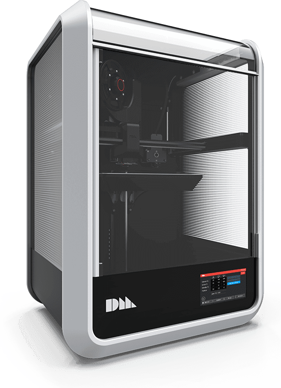
FiberTM is the world’s first desktop 3D printer that lets users build high-resolution parts with the industrial-grade continuous fiber composite materials used in automated fiber placement (AFP) processes. Users can print parts of exceptional strength and stiffness (twice the strength of steel at 20% of the weight), in a broad range of materials that previously required million-dollar AFP systems. All from their desktop.
Parts Stronger than Steel,
Lighter than Aluminum.
Printed on your Desktop
Fiber™ by Desktop Metal is the only 3D printer to leverage Micro Automated Fiber Placement ( µAFP) to produce parts that meet superior performance specifications built with true fiber-reinforced composite materials. The system was inspired by large robotic systems with 5-axis capability used in the aerospace industry to print large airframes made of fiberglass. Using similar fundamentals, Fiber is a 3D printer with a modular µAFP print head system that is powered by a tool-changing platform. It prints parts from two print heads; one using continuous fiber tape; the other using chopped fiber-reinforced filament. With closed-loop heat control, the AFP print head deposits a continuous fiber tape along critical load paths to print dense, reinforced sections, while the second printhead extrudes the chopped fiber filament to print a high-resolution exterior shell.
Key Features
How it Works
Step 1
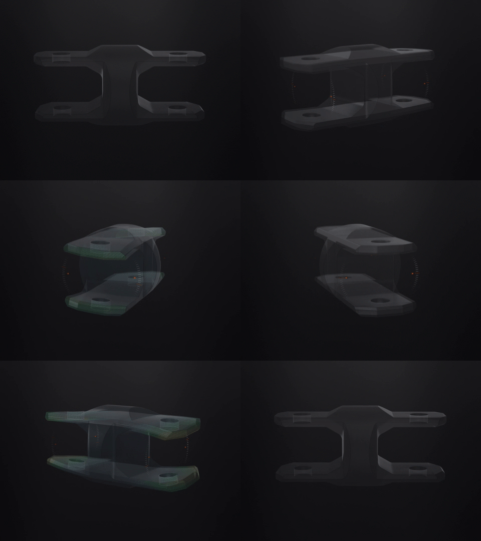
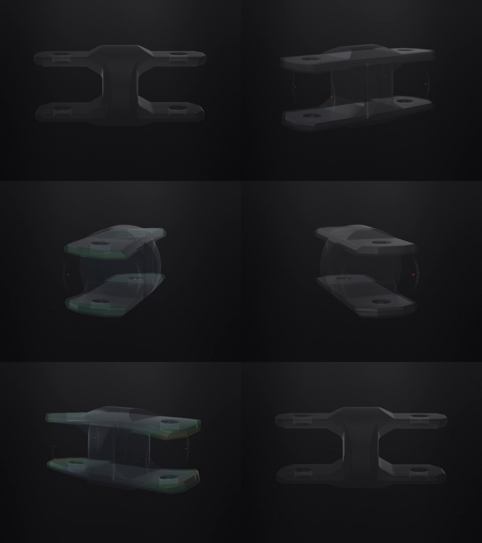
Prepare and Analyze Part Geometry
Prepare and optimize your design for 3D printing by generating geometries, reviewing loading conditions, and identifying areas for reinforcement.
Step 2
Identify Areas for Reinforcement
Selectively reinforce with continuous carbon fiber or fiberglass μAFP tape along critical load paths.
Step 3
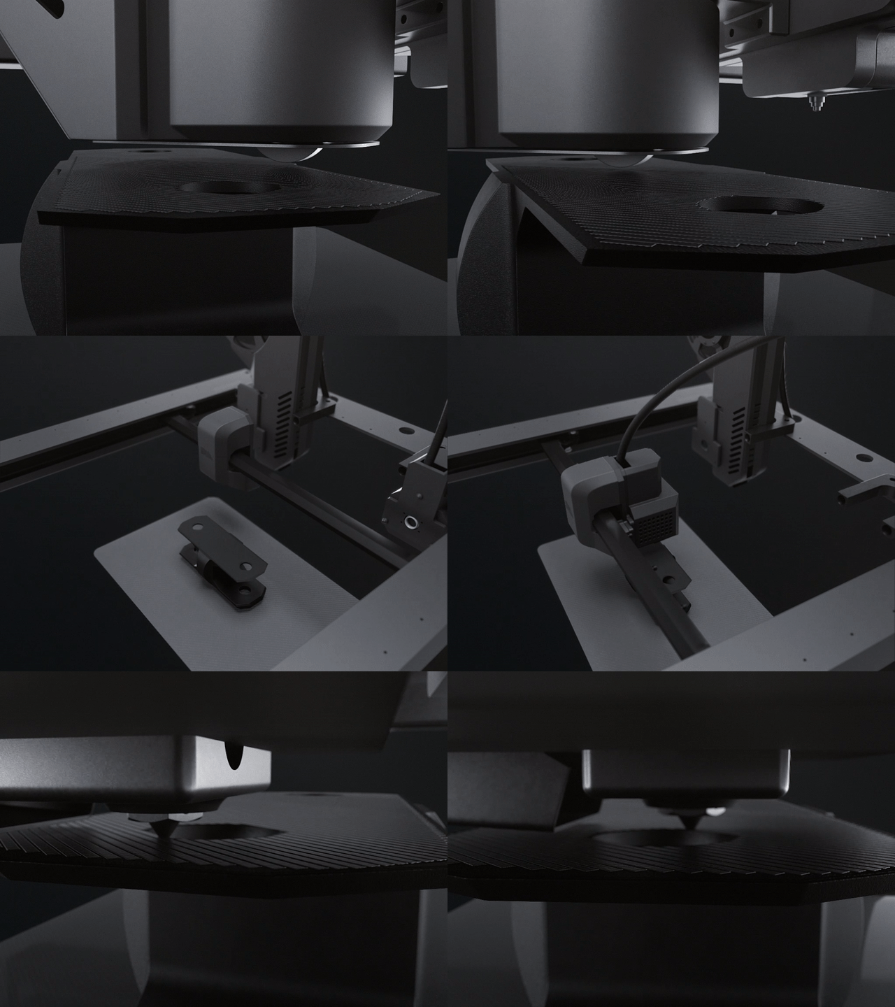
3D Print
A dual-deposition print method to build parts layer-by-layer in both chopped carbon fiber or fiberglass filament and continuous carbon fiber or fiberglass µAFP tape. Fiber™ uses a robotic tool changer to switch between FFF tool head and µAFP tape.
Step 4
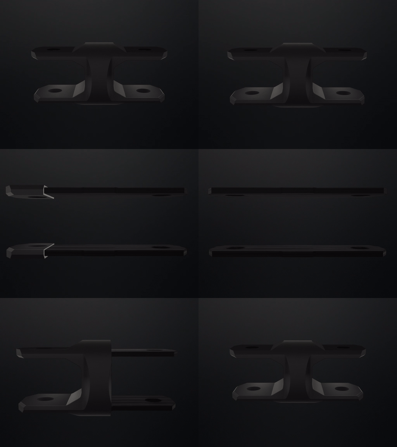
Part Anatomy
Parts printed on Fiber™ feature a chopped fiber shell and solid, continuous carbon fiber or fiberglass reinforcements.
Applications
Strong parts
Continuous fiber reinforcement
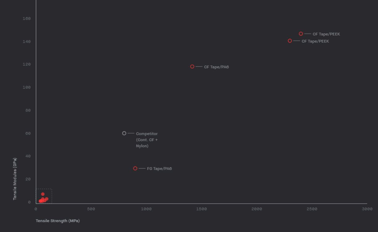
Fiber™ uses prepreg materials uni-directional continuous fiber material systems that combine really high stiffness fibers like carbon, glass, Kevlar, etc with a thermoplastic matrix such as PA6 (Nylon), PEEK, or PEKK. This continuous carbon fiber or fiberglass tape is applied along critical load paths in a process called Micro Automated Fiber Placement (µAFP). Layers of highly loaded continuous fiber tape are laminated to build dense, reinforced sections over three times stronger than steel and as low as one-fifth the weight (up to 2,400 MPa tensile strength and <1.5 g/cc).
Continuous fiber printing expands this landscape to enable stronger, lighter weight components:
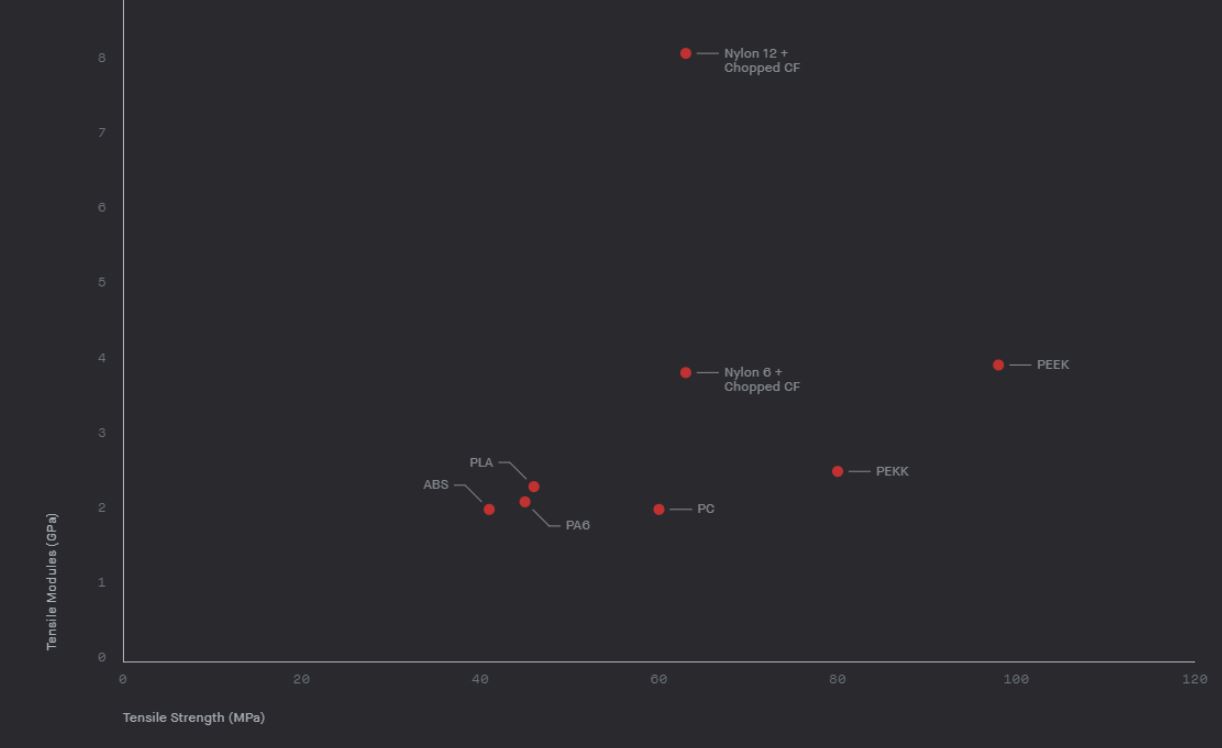
- Over 75x stiffer than ABS
- Over 60x stronger than ABS
Low porosity
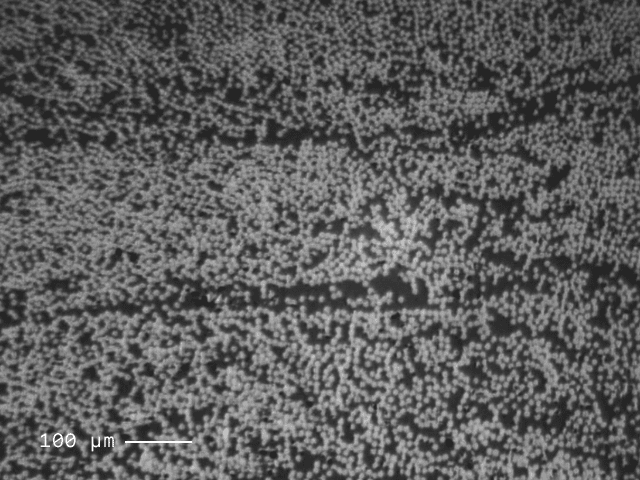
Utilizing continuous fiber tapes made with up to 12k carbon fiber tows or E-glass fiberglass reinforcement, up to 60% fiber volume fraction, and exceptional resin impregnation, Fiber™ is able to achieve continuous fiber reinforcement with less than 5% porosity (or less than 1% porosity for the aerospace industry) which means a higher strength of the printed parts.
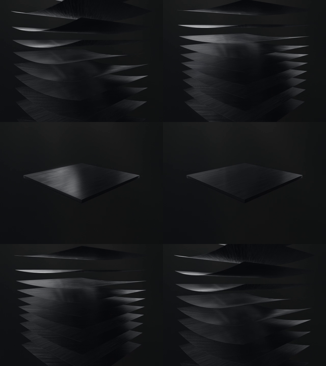
Multidirectional µAFP tape layers
For maximum coverage, with Fiber™ you can automatically optimize where and how much tape to be impregnated or you can enable Expert Mode to customize the orientation for specific loading conditions.
Wide Array of Materials
Fiber™ accommodates a broad set of fiber-reinforced composites, which enables a remarkably versatile range of applications, from consumer electronics to automotive parts. Powered by two print heads: a continuous fiber prepreg tape and a dedicated chopped fiber-reinforced filament.
The prepreg tapes are unidirectional fiber sheets uniformly pre-impregnated with a thermoplastic polymer matrix (PEEK, PEKK, or Nylon PA6). End-use composite parts are manufactured using these prepreg tapes such as fuselage panels, rudders, and elevators in the aerospace industry, or, pressure vessels, pipes in the oil and gas industry, auto parts for the automotive industry, etc.
PEKK + Continuous Carbon Fiber
Description
Characterized by its high tensile and compressive strength, PEKK is chemical-resistant and able to tolerate temperatures above 250°C. When reinforced with carbon fiber, the result is parts of exceptional strength and durability that are ideal for use in extreme environments.
Material Characteristics
PEKK
- Excellent mechanical properties, chemical resistance, and surface abrasion
- Flame retardant
- High compression strength
- ESD-Safe
- Continuous Use Temperature above 250 °C
Carbon Fiber (CF)
- High strength & stiffness
- Low coefficient of thermal expansion
- High fatigue level
- Somewhat brittle
Chopped Fiber Filament

Carbon Fiber
Continuous Fiber Tape

Carbon Fiber
PEEK + Continuous Carbon Fiber
Description
PEEK has superior mechanical characteristics, it is highly resistant to surface abrasion and is heat (above 200 °C) and flame resistant. In combination with continuous carbon fiber, the result is a strong, stiff composite with a remarkable fatigue tolerance that’s perfect for jigs and fixtures.
Material Characteristics
PEEK
- Excellent mechanical properties, chemical resistance, and surface abrasion
- Flame retardant
- Continuous Use Temperature between 200-250 °C
Carbon Fiber (CF)
- High strength & stiffness
- Low coefficient of thermal expansion
- High fatigue level
- Somewhat brittle
Chopped Fiber Filament

Carbon Fiber
Continuous Fiber Tape

Carbon Fiber
Nylon (PA6) + Continuous Carbon Fiber
Description
Carbon-fiber reinforced PA6 nylon is the perfect solution when ESD compliance is required. The composite material displays a tensile strength that is 30 times stronger than ABS, making it an attractive choice for end-of-arm tooling.
Material Characteristics
Nylon 6 (PA6)
- Low cost
- High mechanical strength
- Continuous Use Temperature ~ 100 °C
Carbon Fiber (CF)
- High strength & stiffness
- Low coefficient of thermal expansion
- High fatigue level
- Somewhat brittle
Chopped Fiber Filament

Carbon Fiber
Continuous Fiber Tape

Carbon Fiber
Nylon 6 (PA6) + Continuous Fiberglass
Description
A low-cost composite for fabricating lightweight, high-strength and corrosion-resistant parts, fiberglass-reinforced nylon is well-suited for sporting goods parts that will be exposed to the elements, but require a low cost per part.
Material Characteristics
Nylon 6 (PA6)
- Low cost
- High mechanical strength
- Continuous Use Temperature ~ 100 °C
Fiberglass (FG)
- Low-cost
- Corrosion-resistant
- Non-conductive (insulator)
- No radio-signal interference
Chopped Fiber Filament

Fiberglass
Continuous Fiber Tape

Fiberglass
Material Performance
Cost-effective and Easy to Use
Fiber™ combines the advantages of continuous fiber with the simplicity of 3D printing. Besides advanced composite materials, strong parts and exceptional surface finish, the pricing model of this printer never lets engineers with outdated equipment.
Fiber™ is available in two versions, Fiber LT (low-temperature) for US $3,495/year and Fiber HT (high-temperature) for US $5,495/year. With a 3-year commitment lease plan that includes not only maintenance, consultancy but also machine updating, you’ll never have to worry about outdated equipment.
In just a few minutes and at the press of a button from the comfort of their desktop, engineers can now 3D print high-quality industrial-grade composite parts, due to Fiber™’s entry-level settings and opt-in advanced controls.
Part Gallery and Application Examples
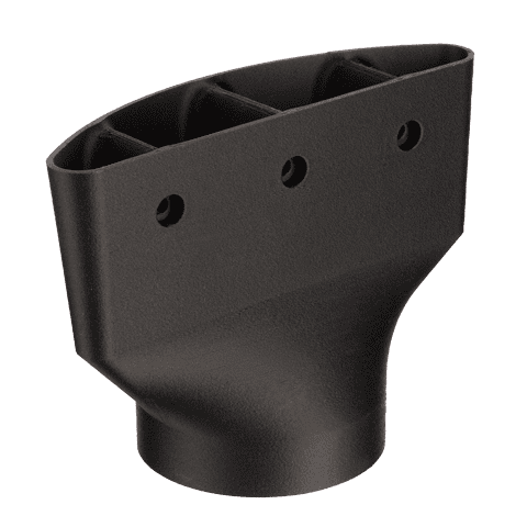
Brake Duct
Material: PEEK + Carbon Fiber
Found on a BMW hill climb car, this duct reroutes air from the front of the car to cool its brakes.
Full Description
Printing on Fiber enables optimization for the most efficient airflow, leading to better cooling. Brakes get extremely hot during competition, PEKK + CF provides heat resistance and is lighter than an aluminum alternative.
Specs
Application
- End-Use Parts
Technology/Process
- Desktop Metal Fiber / Material Extrusion
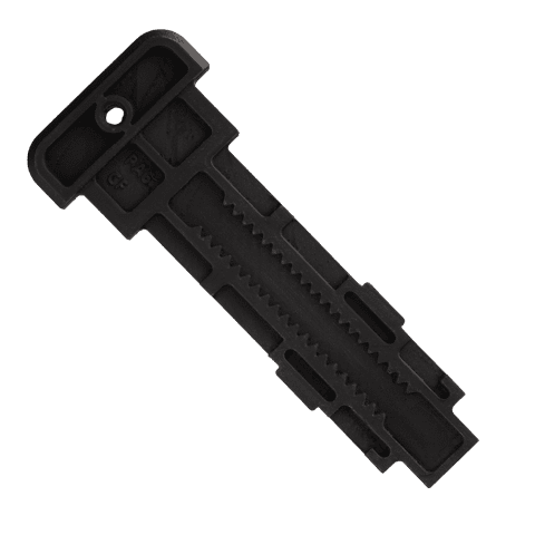
Ski Binding
Material: PA6 + CF
The ski binding heel track attaches to the base plate on a ski, allowing the heel binding to be adjusted.
Full Description
Ski bindings need to be extremely stiff to withstand the forces experienced by the ski as it turns, making composites an ideal choice. Using Fiber™, manufacturers can prototype this part before it is mass-produced via injection molding.
Specs
Application
- End-Use Parts
Technology/Process
- Desktop Metal Fiber / Material Extrusion
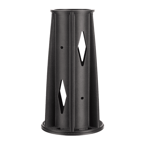
Rocket Tail Cone
Material: PEEK + CF
The rocket tail cone sits at the end of a rocket, redirecting air for optimal aerodynamics.
Full Description
This part has to withstand the extreme heat of a rocket engine, so it must be fabricated using a high-temperature material like PEEK. With the design freedom of Fiber, engineers were also able to add complex features to improve aerodynamics.
Specs
Application
- End-Use Part
Technology/Process
- Desktop Metal Fiber / Material Extrusion
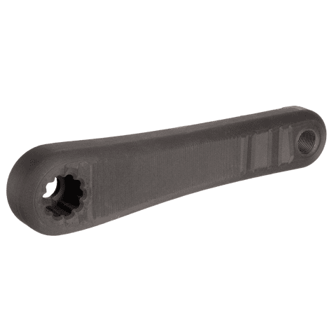
Bike Pedal Crank
Material: PA6 + FG
This part is the connecting arm responsible for attaching a pedal to the rear wheel crankset of a bike.
Full Description
Shedding weight is critical for performance bikes. Composites are an ideal choice for bike components like this due to their high specific strength and stiffness.
Printing on Fiber in fiberglass-reinforced PA6 allows for the manufacture of a corrosion-resistant, low-cost, functional prototype without the typical labour-intensive process of hand layup.
Specs
Application
- End-Use Parts
Technology/Process
- Desktop Metal Fiber / Material Extrusion
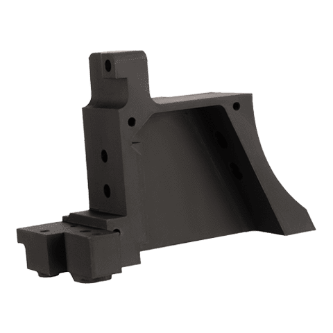
UHF Housing
Material: PEKK + CF
This part is an ultra-high-frequency radio housing for use in a CubeSat.
Full Description
Due to the extreme temperatures, this part will face in space, this part was printed using PEKK.
Printing this part allowed the CubeSat team to quickly iterate on the design in its intended material, and produce multiple variations in a matter of days. The complex geometry and small features of this part, make it ideal for printing.
Specs
Application
- End-Use Parts
Technology/Process
- Desktop Metal Fiber / Material Extrusion
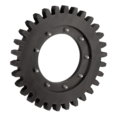
Balance Shaft Gears
Material: PEKK + CF
This part is a balance shaft gear used in an automotive turbocharger to reduce vibration.
Full Description
Printing in PEEK delivers a lighter part compared to metal counterparts, while still meeting the strength and heat requirements.
With the ability to print industrial-grade composites like PEEK with continuous carbon fiber reinforcement, Fiber™ allows engineers to print parts that can stand up to high temperatures and have unrivalled part strength – without spending tens of thousands of dollars.
Specs
Application
- End-Use Parts
Technology/Process
- Desktop Metal Fiber / Material Extrusion
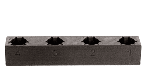
Shroud Holder
Material: PA6 + CF
This fixture is used to hold metal injection molded shrouds for secondary machining operations.
Full Description
Designed to hold metal injection molded shrouds in place as an articulated robot picks them up and places them in a CNC fixture. This part features customized geometry that conforms to the shrouds’ shape.
Due to their stiffness and wear resistance, composites are ideal for this part.
Specs
Application
- Jigs & Fixtures
Technology/Process
- Desktop Metal Fiber / Material Extrusion
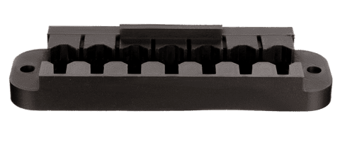
Machining Fixture
Material: PEEK + CF
This machining fixture holds lock barrels in place during a secondary reaming operation.
Full Description
To achieve desired tolerances, metal injection molded (MIM) parts, such as lock barrels, often require secondary machining operations. The fixtures for these operations must be very stiff to hold lock barrels steady while experiencing the forces and vibration of the reamer.
By printing the part on Fiber, the fixture can be manufactured overnight, with similar material properties to aluminum thus saving both time and money.
Specs
Application
- Jigs & Fixtures
Technology/Process
- Desktop Metal Fiber / Material Extrusion
Technical Specifications
Print Technology |
Print TechnologyMicro Automated Fiber Placement (μAFP™)Fused filament fabrication (FFF) |
Print System |
Print SystemCoreXY with robotic tool changer |
Max. Build Rate |
Max. Build Rate20 cm3/hr (1.2 in3/hr) |
Layer Height |
Layer Height130 µm - 250 µm |
Build Envelope |
Build EnvelopeFFF: 310 x 240 x 270 mm (12.2 x 9.4 x 10.6 in)µAFP™: 230 x 230 x 270 mm (9.0 x 9.0 x 10.6 in) |
Build Plate |
Build PlateHeated up to 149 ºC (300 ºF) |
Nozzle Diameter |
Nozzle Diameter0.40 mm |
Software |
SoftwareFabricate® Cloud (desktop options also available) |
