Live Sinter
DESKTOP METAL™
Live Sinter™
Simulation software to predict & correct warpage or cracking during the sintering process
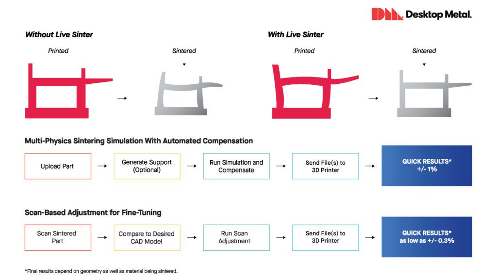
Live Sinter™, developed by Desktop Metal, is a breakthrough simulation software designed to reduce the trial and error often involved in the sintering process of the metal 3D printed parts made with the binder jetting additive manufacturing process. Rather than printing a part straight to have it warp out of spec, Live Sinter prints an oppositely warped part that will sinter to meet dimensional tolerances.
Own Physics with Live Sinter.
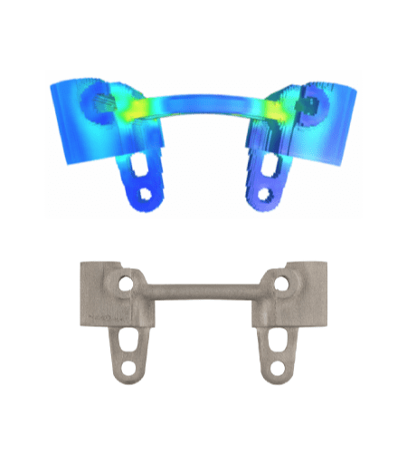
Live Sinter uses a multi-physics engine. The software simulates the complex forces and deformation that parts experience during sintering. As a result, it will generate a “negative offset” geometry in just minutes, which, when sintered, results in true-to-CAD parts out of the furnace.
- Predict furnace deformation
- Automatically generate print geometry
- Parts emerge from the furnace true to CAD
Features
Why is Live Sinter a must-have simulation software?
Decades-old sintering challenges
Sintering remains one of the main challenges to the broad adoption of metal binder jetting technology. However, it is used in metal injection molding or pressed and sintered to fabricate millions of parts each year. Desktop Metal’s advanced simulation software team designed Live Sinter to eliminate the trial and error required to achieve high-accuracy parts via powder metallurgy-based additive manufacturing processes.
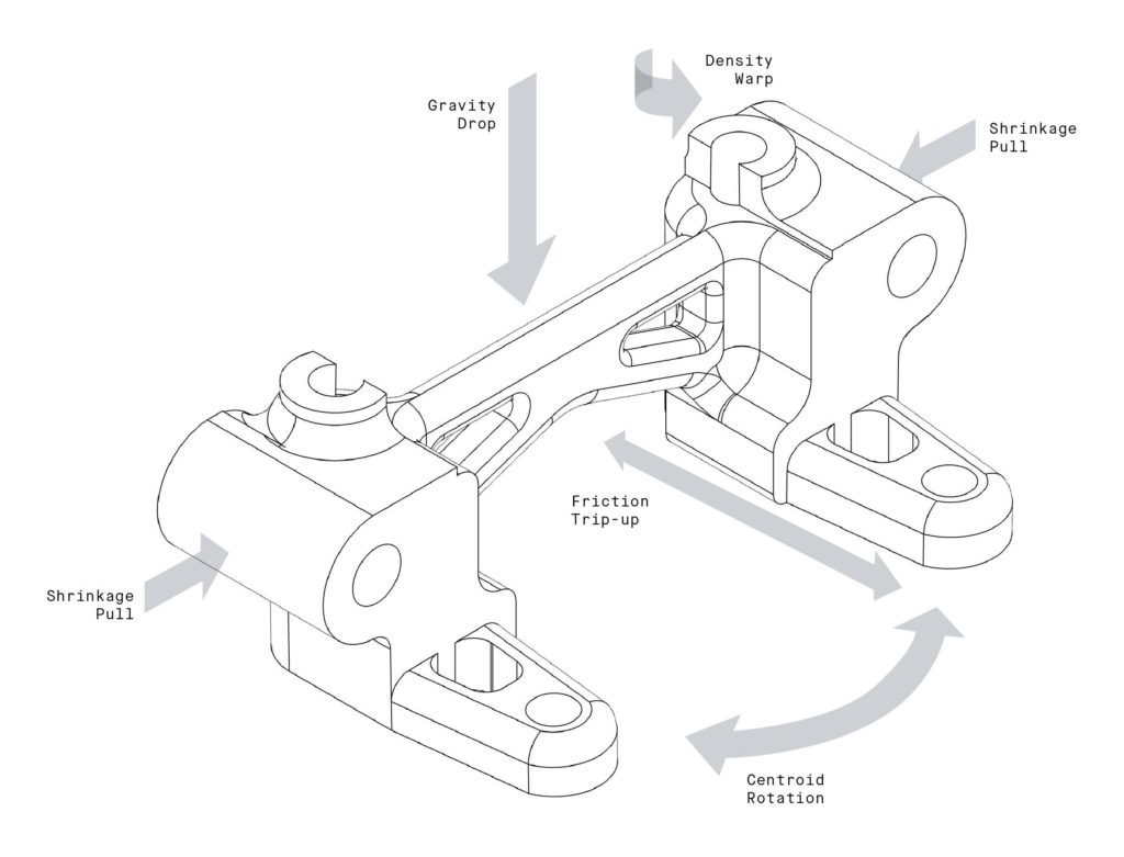
The compounding dynamic forces represent the typical unwanted situations during the sintering process, and those are:
- Part deformation
- Shrinkage
- Stress concentration
- Cracking
- Varying densities
How does Live Sinter work?
The two primary functions of the Live Sinter process:
- Sintering Simulations
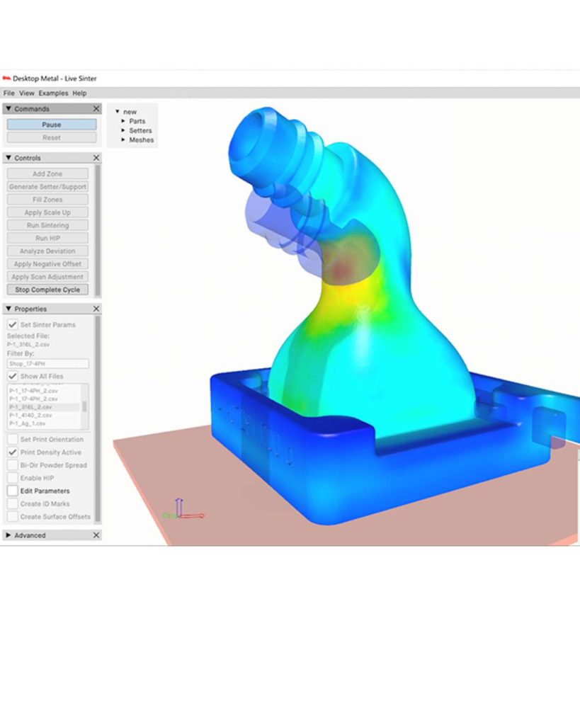
- Live Sinter simulates the shrinkage and distortion of a metal part during sintering. The application models non-linear shrinkage, friction, elastic and plastic deformation, and density variations caused by powder spreading. Interactive simulations provide in-depth views of factors such as stress, strain, and powder density.
- Negative offset
- Using that information, the software then generates a “negative offset” geometry to compensate for the distortion. This “negative offset” geometry is sent to print and when sintered, the results are in a true-to-CAD part out of the furnace.
Extra Features available with Live Sinter
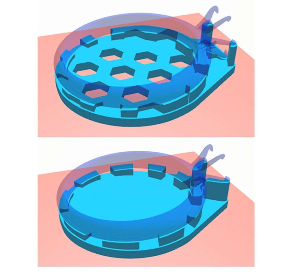
Optimized Support Generation & Surface Offsetting
Live Sinter provides optional support generation optimized to significantly reduce material usage while enabling distortion compensation to occur where needed. Users interactively generate supports in various sinter orientations while analyzing support volumes and stability characteristics as part of a trade-off analysis. Surfaces to be offset for downstream machining operations may also be specified for integrated manufacturing operations.
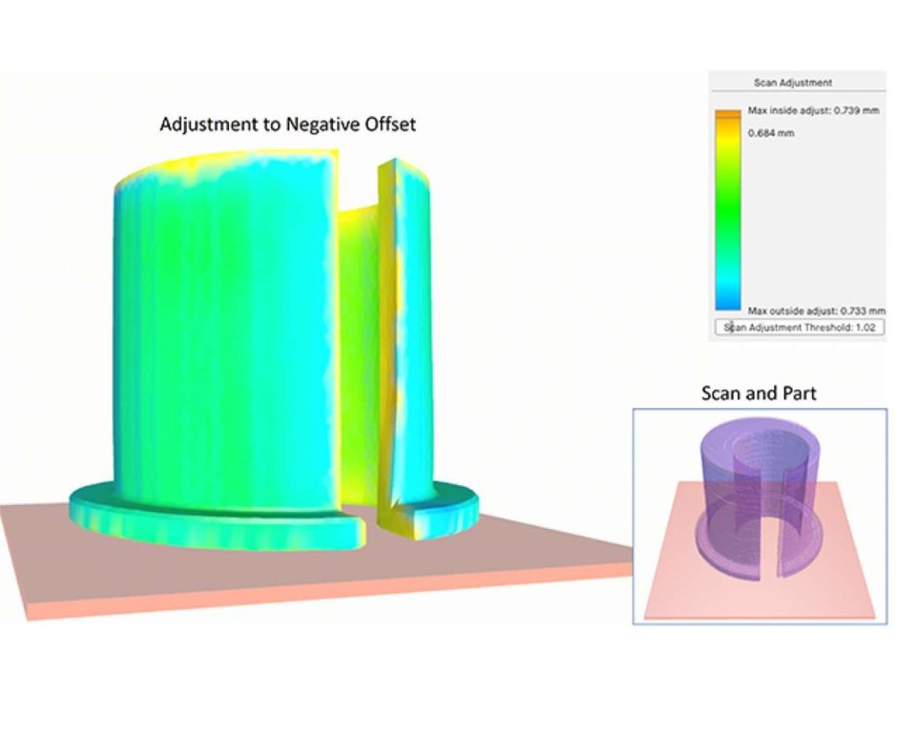
Scan-Based Adjustment for Fine Tuning
Scan adjustments work over the volume of the part, ensuring that thin walls and hidden interior regions move in concert with exterior regions. Live Sinter enables correcting for complex distortion effects, yielding parts that consistently fall within 1% of the target dimension with as low as +/- 0.3% deviation. Parts may be scan adjusted multiple times to reach higher levels of accuracy.
Examples
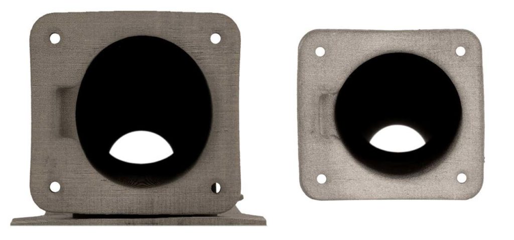
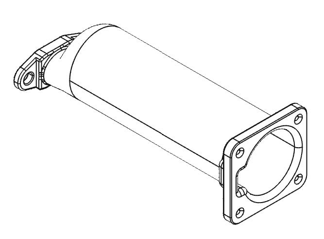
Heater body element for Desktop Metal Carbon Fiber Printer
- Steel part subjected to high temperatures
- It required 3D printing due to its complex geometry
- Adding support to the cylinder cavity was not possible – as it used to get stuck
- Flange ends warp due to density variations
- 86 mm long part falls within 0.2 mm tolerances
With Live Sinter all of the above challenges were overcome.
|
