Clear And Texture Together
Part three of this tutorial helps printer operators who aren’t graphic artists get the absolute most out of their multi-colour, multi-material 3D printers, like the Stratasys J750. We will cover how to create models with semi-transparent textures wrapped around curved, transparent bodies (taking advantage of a new slicer from Stratasys), and how to fix UV-mapping problems when wrapping 2D textures around 3D bodies goes wrong.
Step 1: Overview
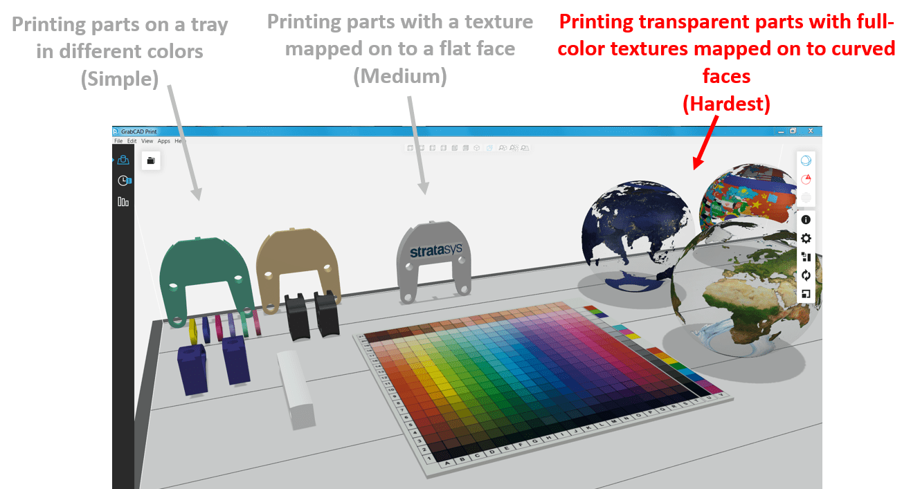
Today we will tackle what was previously described in the first tutorial as the most difficult type of full-colour thing to print: semi-transparent textures wrapped around curved, transparent shapes.
This is a crucial skill for anyone who prints 3D consumer goods (sports or perfume bottles with logos over clear parts), electronics mock-ups (full-colour displays over or under clear screens) and even mementos or figurines (3D printed sports trophies, miniatures or museum reproductions encased in a block of clear plastic).
Keep in mind that printing with clear+textures in the same model requires the new Advanced Slicer capability for Stratasys J750 printers, currently in beta. So if you do not have a J750, don’t want to be on that beta, or are just here to explore UV mapping, consider skipping ahead to step 5. Let’s begin!
Step 2: Making Areas Of Texture Image Transparent
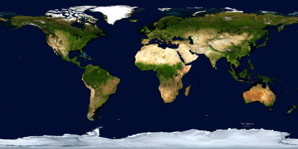
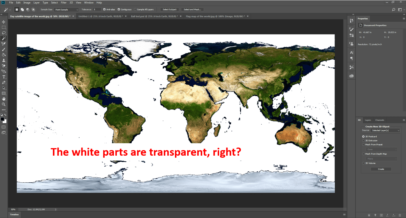
In the below example, a satellite image of Earth is used that will be wrapped around a sphere to create a semi-transparent globe:
If I didn’t do anything to make parts of that image see-through, we’d end up with that map wrapped around the entire globe, with no way of seeing that the interior of the globe was clear. We could’ve done it in Photoshop, after reading just part 1 of this series.
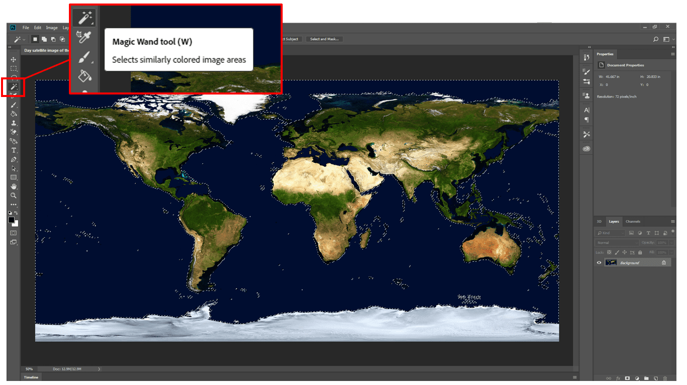
Now, open that image in Photoshop and use the magic wand to select the colour of the ocean.
After hitting “cut” (or CTRL-X or Delete) to remove the selected oceans, then the white parts of my image are transparent, correct?
Not as of yet. In Photoshop, transparency is denoted by a small grey and white checkerboard pattern in an area, not white. Here’s what it would look like on a different world map with the oceans cut out of (kind of):
This is a simple way to check – if you export both images as PNGs and put them over any shape in PowerPoint, it’s simple to see what is transparent and what isn’t:
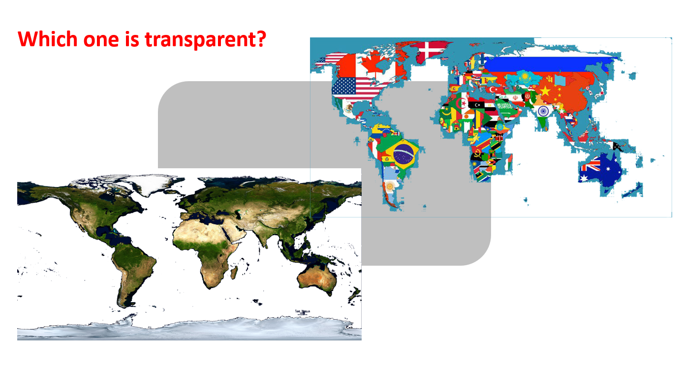
That’s a good check to do early on, to ensure your texture image will let the rest of your transparent 3D printed model to shine through. So how do we get that checkerboard?
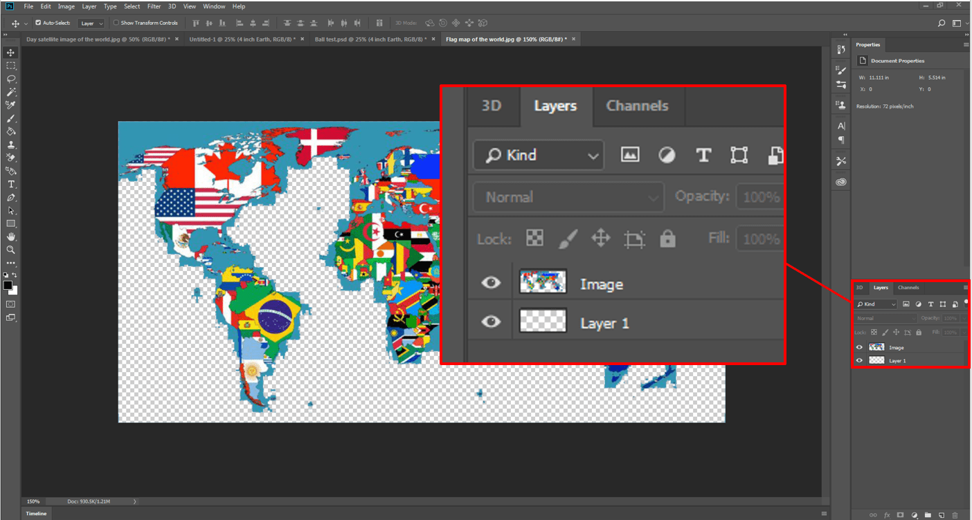
You don’t need to be a Photoshop expert, so here is the simplest way found:
- Open image in Photoshop, which will be the background layer.
- Right-click on that image layer and make a duplicate of it (due to background layers not being transparent)
- Add yet another empty layer and drag it underneath your duplicate, it doesn’t matter what it’s called (this will be a transparent checkerboard background).
- Delete your original background layer
- Only then start magic-wanding and removing areas of the top layer you don’t want
Again, this saves time from having to change the size of the original image, or do anything else out of the ordinary, and it gives a transparent checkerboard layer at the bottom to see if it is working.
You can also right-click on the background layer and use the command “layer from background” to easily accomplish steps 2-4 above.
You’re looking to have your desired image on one layer, with an empty and transparent layer below it:
This was done with the original satellite image, and after a lot more magic wand, you’ll be ready to export the PNG.
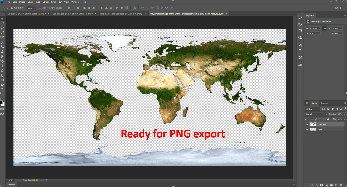
So now the question is, why export a PNG and not a JPEG or bitmap? This is because PNG’s have what is called an “Alpha Channel’, or a designation where specific areas of the picture will be transparent or not. In fact, you can see a wide difference right in the Photoshop Export dialogue:
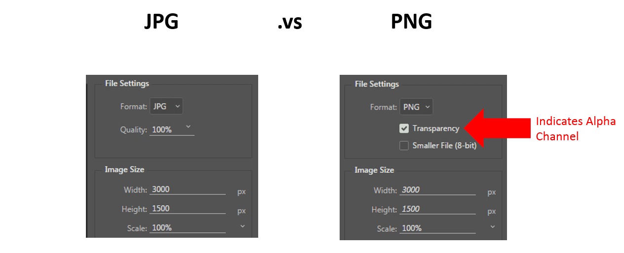
Save the image as a PNG only for the next steps to work.
Now that we’ve got an alpha-channel-enabled texture, that’s opaque in parts and transparent in parts, ready to lay over your 3D shape. Let’s take a look at how to do that next.
Step 3: Mapping your 2D texture over a 3D shape
Now, you’ve got a 2D (probably rectangular) image ready to map over a curved 3D shape.
If we attempt to do the simple steps done in part 1, you’ll get a bad mapping.
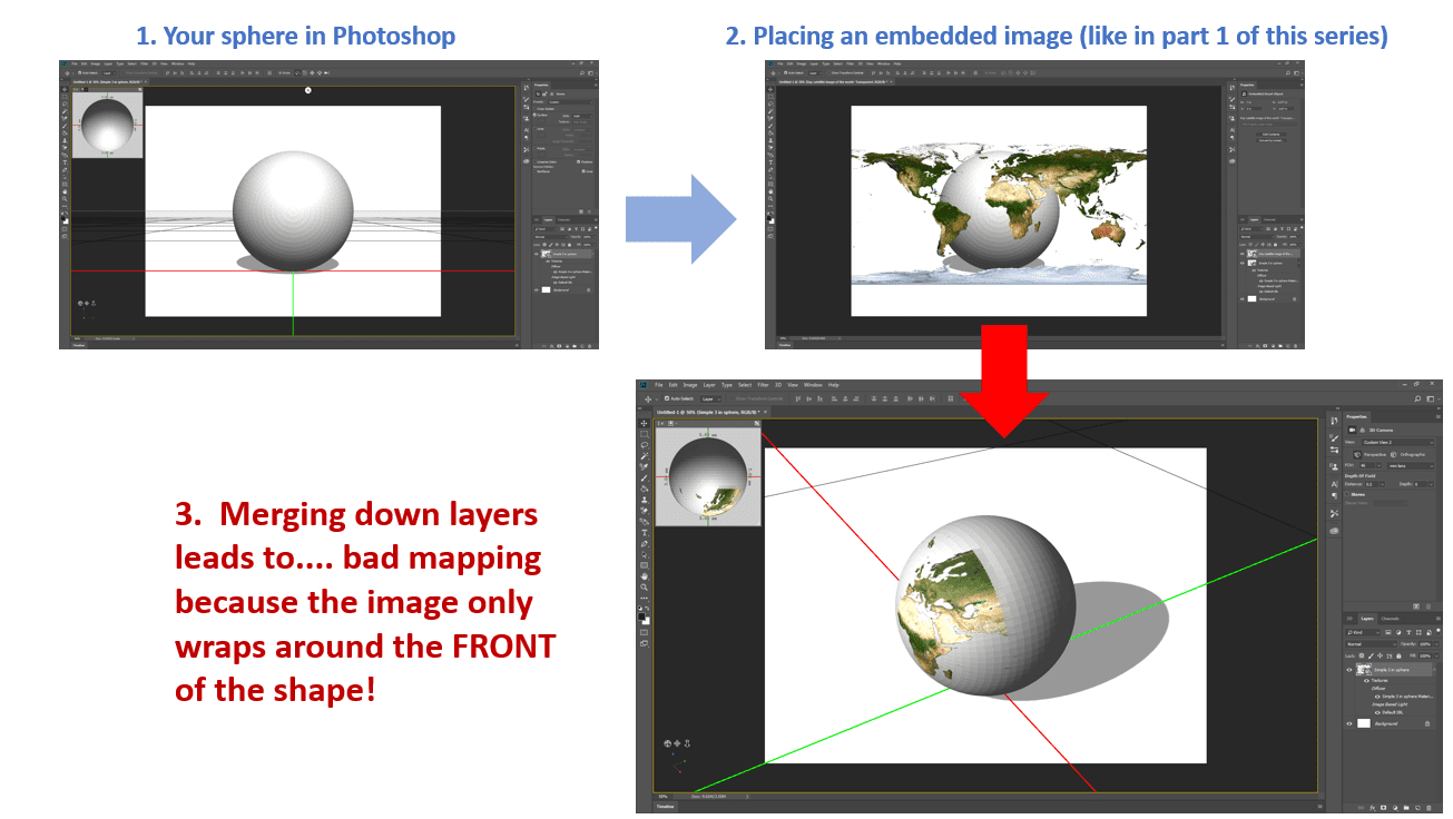
We now have to go deeper in order to find a way to tell the image how to wrap around our entire shape, and that is called UV mapping.
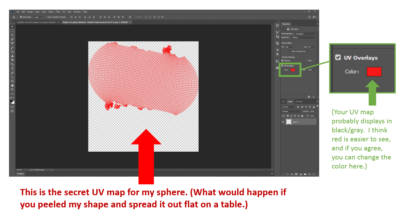
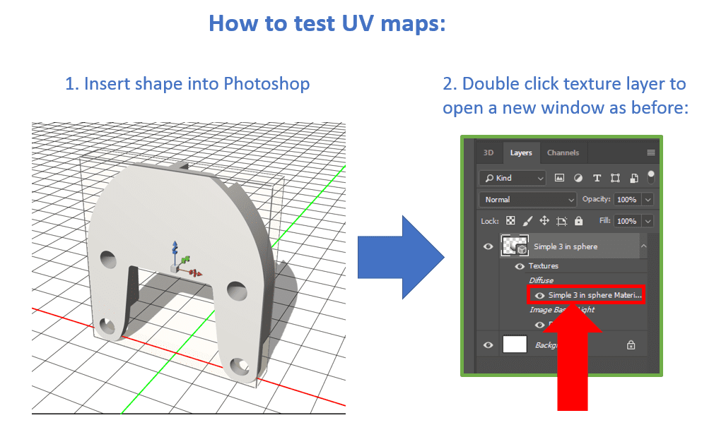
After you have your sphere (or another complex shape) in Photoshop, to find Photoshop’s secret UV map for your shape, click on the name of the texture inside your 3D layer.

Another window will open in Photoshop to show you your UV map:
Now that we have got a 2D representation of our 3D object, you can use your 2D map image created earlier.
Embed your image into this new window (as we learned in the first tutorial) and resize it to fit the UV map as best as you can, as it will never fit perfectly.
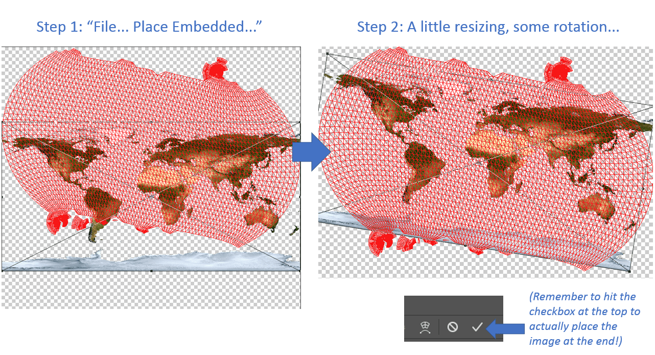
After hitting the checkbox, your image is now part of the UV map.
It’s important to keep in mind that you hit “File…Save” while in the UV map window or you will not see the results in your main 3D part window!
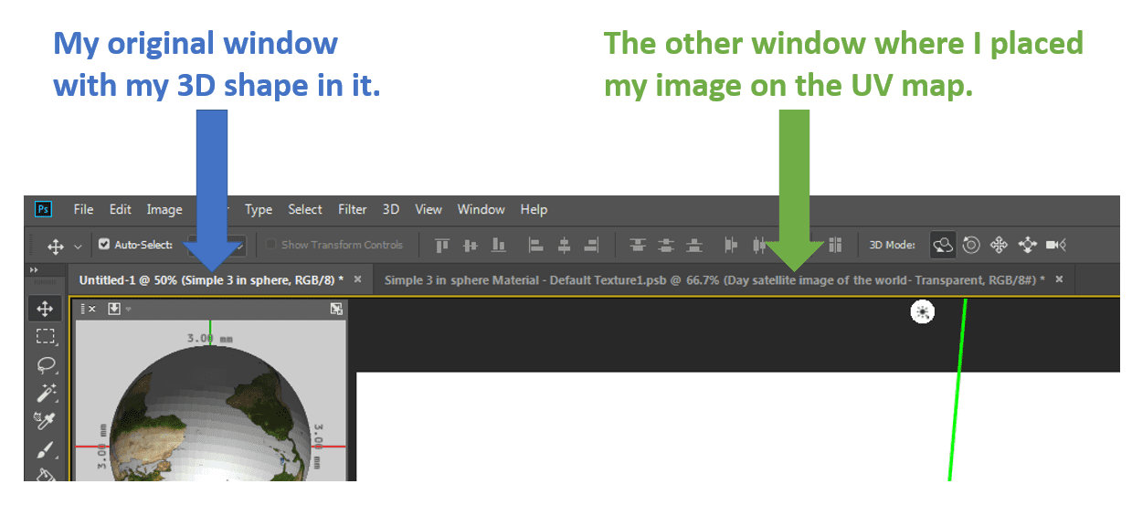
Your 3D part image in another window will update the moment you hit “file…save” in the UV map window:
And just to point out the difference between the two windows more clearly:
Now you have a decently textured solid, and that texture is transparent in certain parts.
But if you want the solid areas of your model to actually print transparent in the final physical result, you have to do one more, counter-intuitive step: making everything transparent.
Step 4: Importing Semi-Transparent Models Into GrabCAD Print
In Photoshop, you now have got a 3D model where you can see the texture all around it:
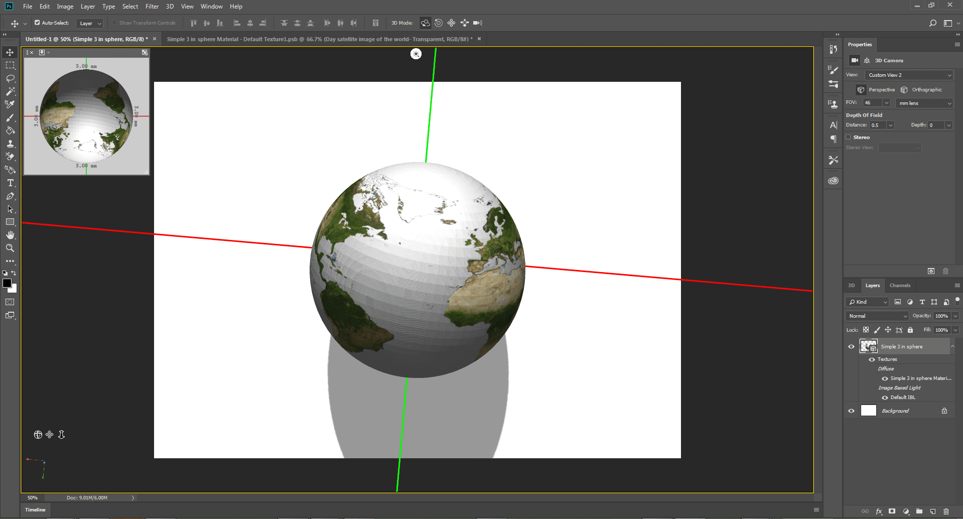
That image is transparent in parts (which is why you can see the white STL tessellation where the oceans should be).
However, for GrabCAD Print’s new Advanced Slicer to register that you want the body of your model to print in clear under your image, you have to make the entire part transparent in Photoshop, including the texture – which is weird.
But that’s what the Advanced Slicer required to read the VRMLs in as of this point.
To make your solid transparent, head over to the 3D toolbox on the lower right and single click on the material.
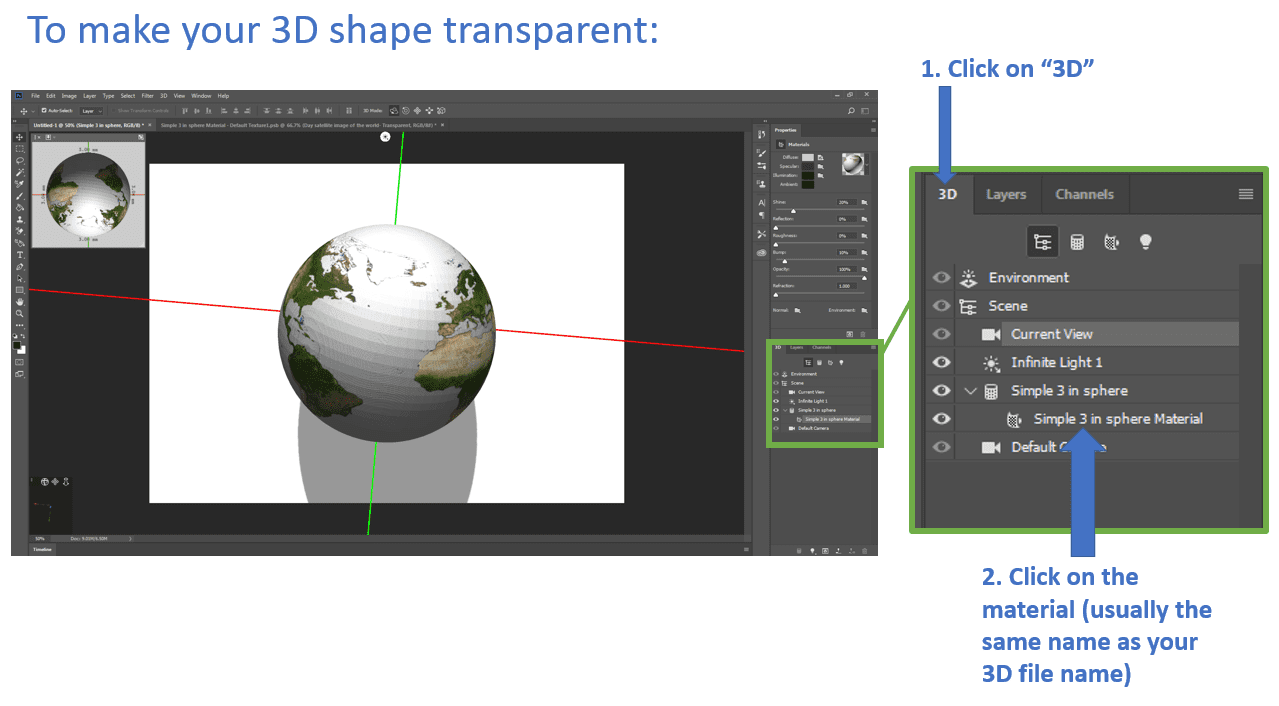
Turn the Opacity slider all the way down:
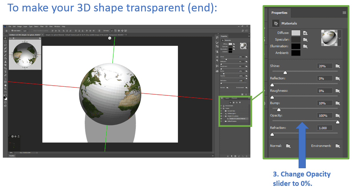
Now on the screen, you should see nothing. But your 3D shape is still there, promise!

Now, such as in part 1, save your 3D layer out as a VRML to get it into GrabCAD Print. But this time, you can only choose PNG as your type of texture format:
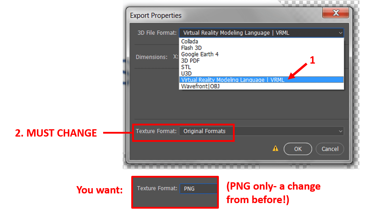
This is a change from part 1, where JPG or BMP texture format VRMLs were also acceptable. Only PNG VRMLs seem to be successful with transparent printing.
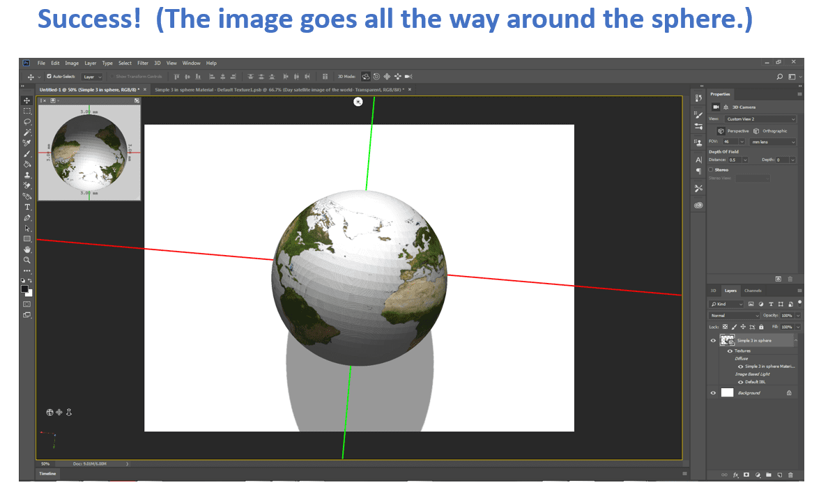
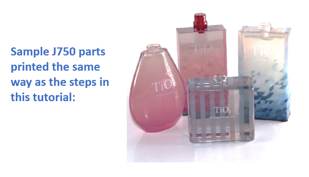
Finally, when importing those VRMLs into GrabCAD Print, they will show up as clear bodies with texture wrapped around the outside of them as you intended:
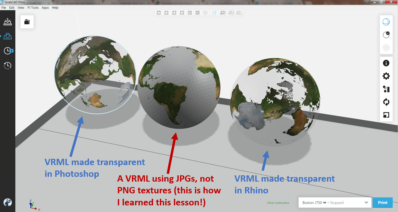
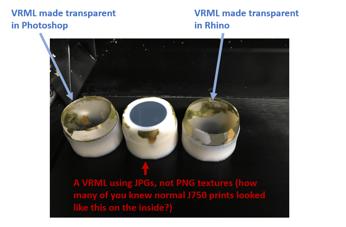
Those models look good on the tray (try rotating your view) and print out the same way (the example stopped this print at 75% of the way through so you could see the insides)
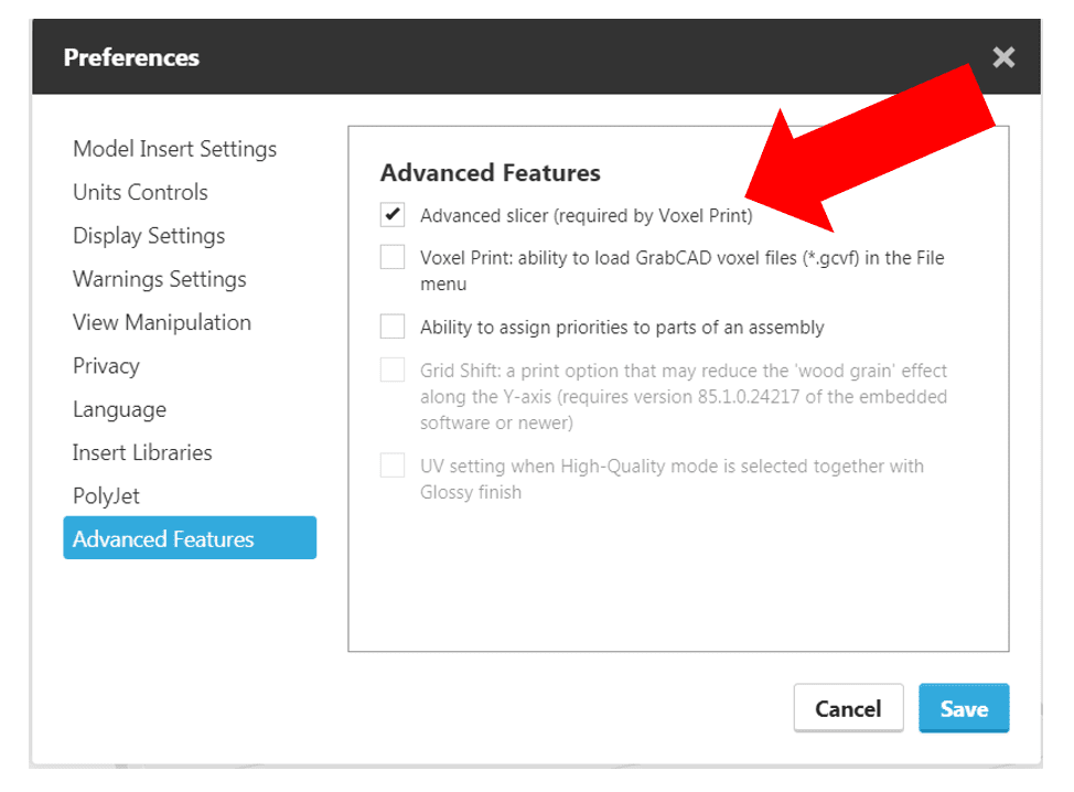
If you can not see the transparency of your models on the tray and you are positive you have done all the previous steps correctly, check that you have the Advanced Slicer turned on under GrabCAD Print’s “File..Preferences…Advanced Features”:
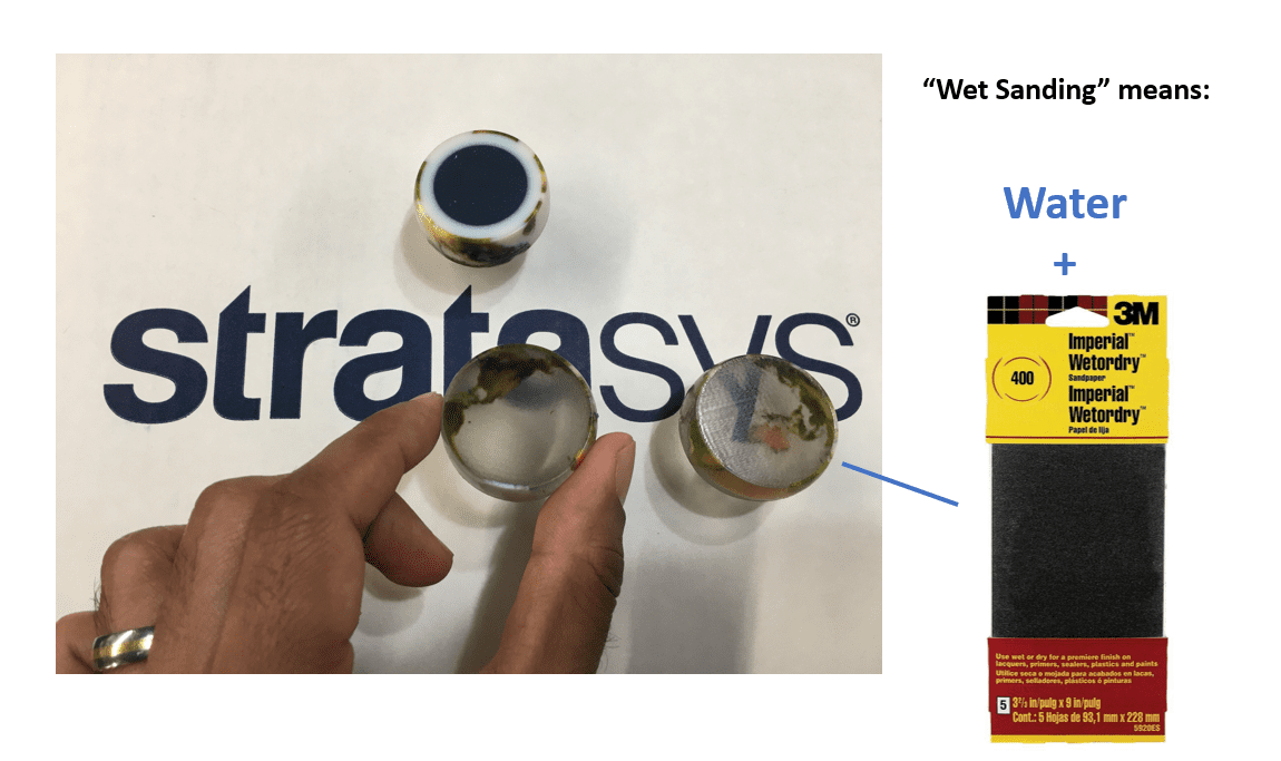
With a bit of hand-polishing and wet-sanding with 400 grit sandpaper (which I haven’t done enough of yet), those clear parts begin to shine and you can even see right through the globes:
After that image I did about 10 more minutes of wet sanding and then finally learned why experienced operators always suggest spraying clear coat on PolyJet models:
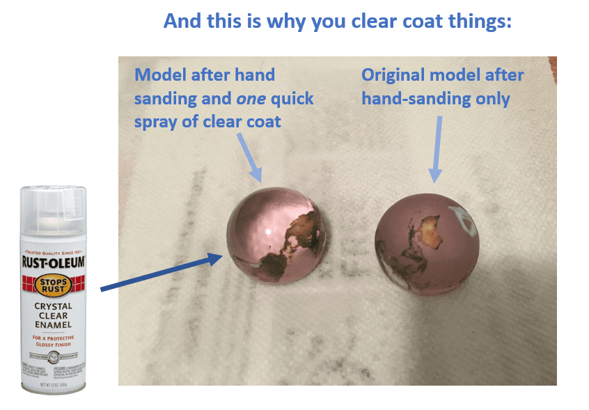
Unreal, isn’t it?
Prior to the Advanced Slicer, you could only print models like that solid white globe with the solid blue core, or like assemblies of STLs where each STL was only a single solid colour. However, now we can combine Transparency + Texture for the first time.
So, we did a simple rectangular texture-mapped around a simple 3D shape (a sphere).
What will happen if you have to wrap textures around something more complex? And they get all stretched out or disjointed?
Step 5: Repairing Bad UV Maps
Why is it called UV Mapping anyway?
U and V are axes in the direction you could walk if you were to be standing on a surface of your model, and they chose those letters due to the directions X, Y and Z were already taken. Doing a full tutorial about UV mapping would be out of scope in this situation (and there’s a vast majority of them on YouTube), so for today, therefore, we will focus on two parts:
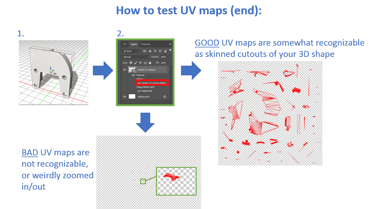
- How to tell if you have a bad UV map
- How to automatically make a new, hopefully, better, UV map
The program used to check UV maps is Photoshop since SOLIDWORKS cannot do it. It’s simple to reveal the secret UV maps in PS once you know where to double-click.
Both good and bad examples are from the same CAD file, saved out as an STL from SOLIDWORKS on two different days. Why was there a bad map one time and not the other? There must have been some kind of STL export setting, but the error could not be repeated. We have to just deal with it now.
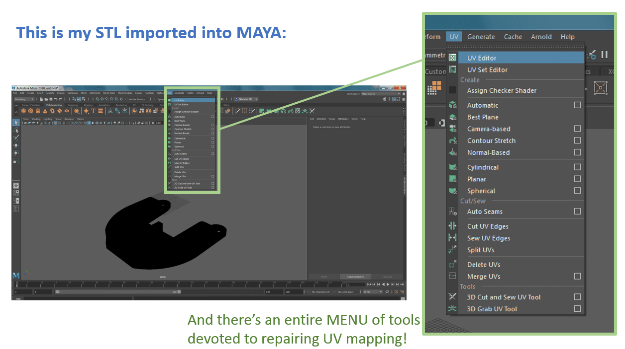
Photoshop does not seem to have an easy way to repair bad UV maps. The thing that couldn’t work in Photoshop seemed to be just a few clicks away in Maya.
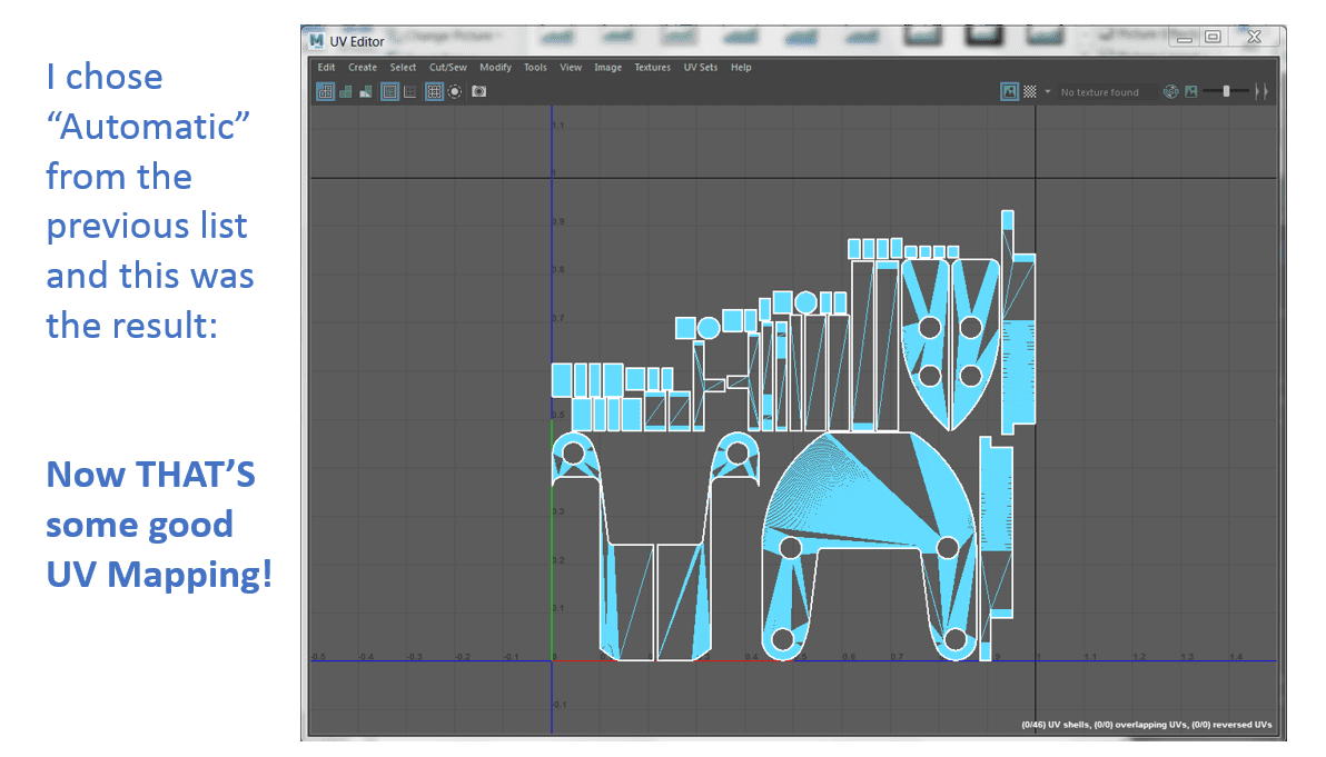
That image is perfection. You can clearly see where each piece comes from my 3D model, it is all lined up and nested (remember how off-kilter even the ‘good’ mapping was in Photoshop?). You can not ask for a better unwrapping than that!
You obviously can not save VRMLs out of Maya (as of Maya 2016) and the install was having trouble saving out STLs. so save out an .OBJ file (mentioned in the first tutorial).
Bring that OBJ into Photoshop like any other 3D file, and look at the UV mapping below:
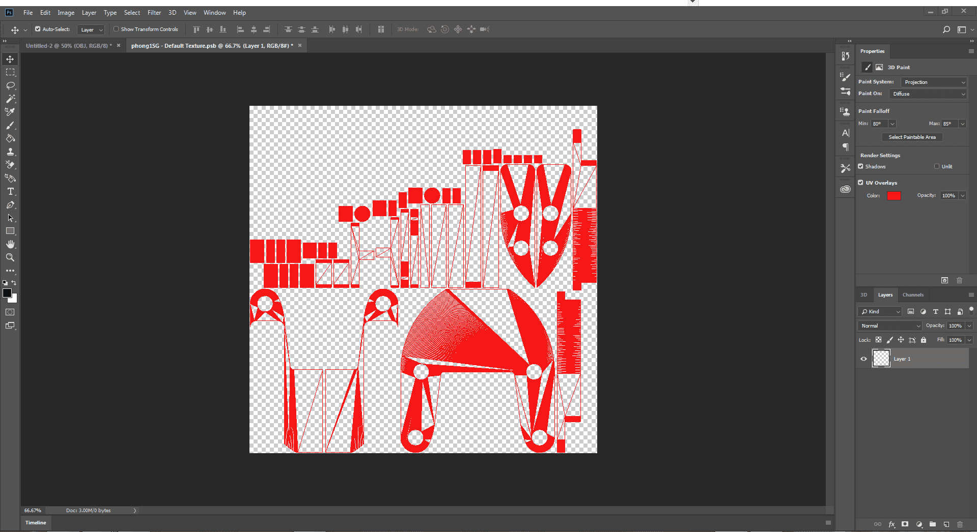
Although not everyone has Mata, it’s good to know that there is at least one program out there that can do nearly perfect, effortless UV unwrapping of damaged 3D CAD files out there. If you hit this issue frequently, consider a Maya license.
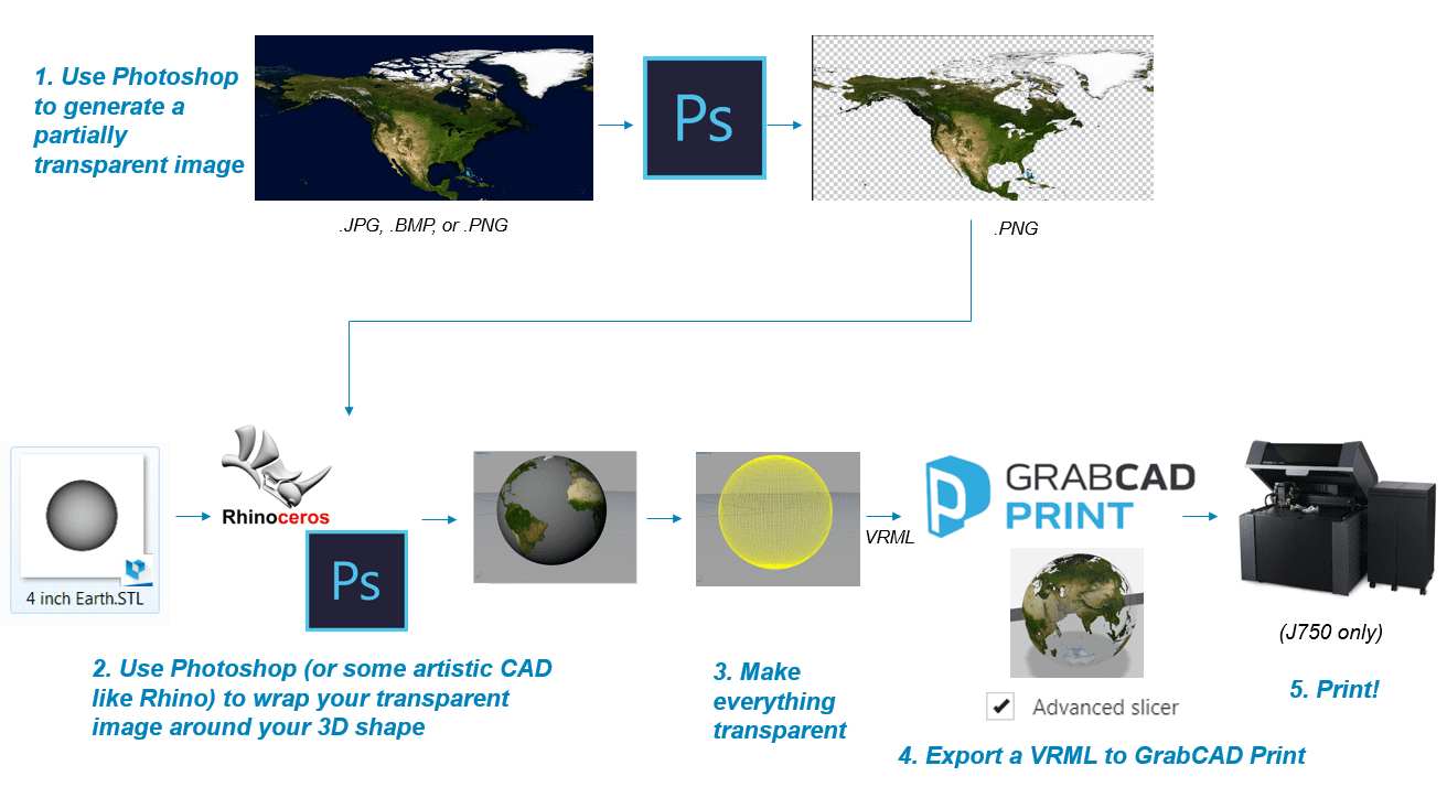
To recap, here is the workflow followed:
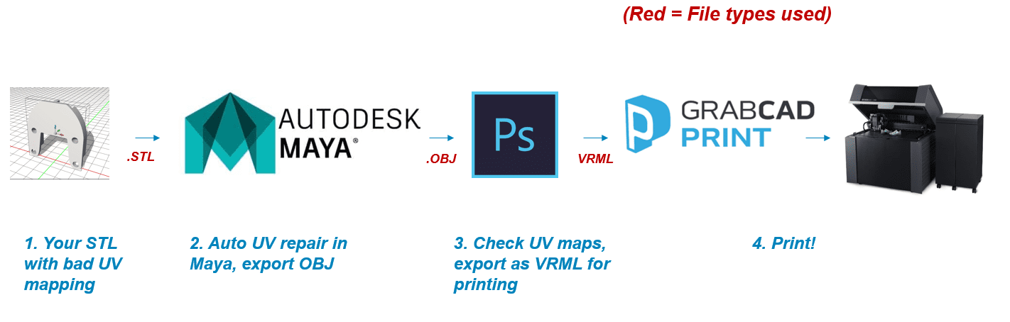
Most times, you will have to do that, but now you know just in case.
Step 6: Final Thoughts
What a long way we have come thus far from these three tutorials. From not even knowing what a VRML was, now you know how to lay and merge simple flat textures onto them (in Photoshop), how to open and scan them for common errors (in Microsoft Word), and even, how to wrap textures around complex surfaces, repairing UV maps if required (in Maya and then Photoshop again).
If you’re specifically a SOLIDWORKS user, there is a better texture mapping software right inside your CAD system called Visualize.