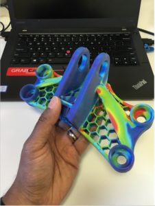
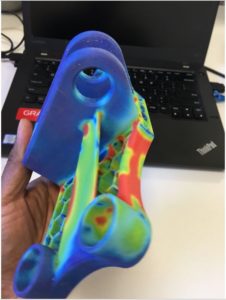
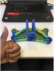
What if you could see, feel, and handle your FEA (Finite Element Analysis) results in the best way to share them with colleagues and students? The below tutorial goes through the steps on how to properly use SOLIDWORKS Simulation and GrabCAD Print in order to print full-colour FEA results on PolyJet colour printers, like the Stratasys J750. It’s far more simple than one would think it is.
Step 1: Run An FEA Analysis
To begin, get a model to analyze, or even from GrabCAD. The following is a sample file:
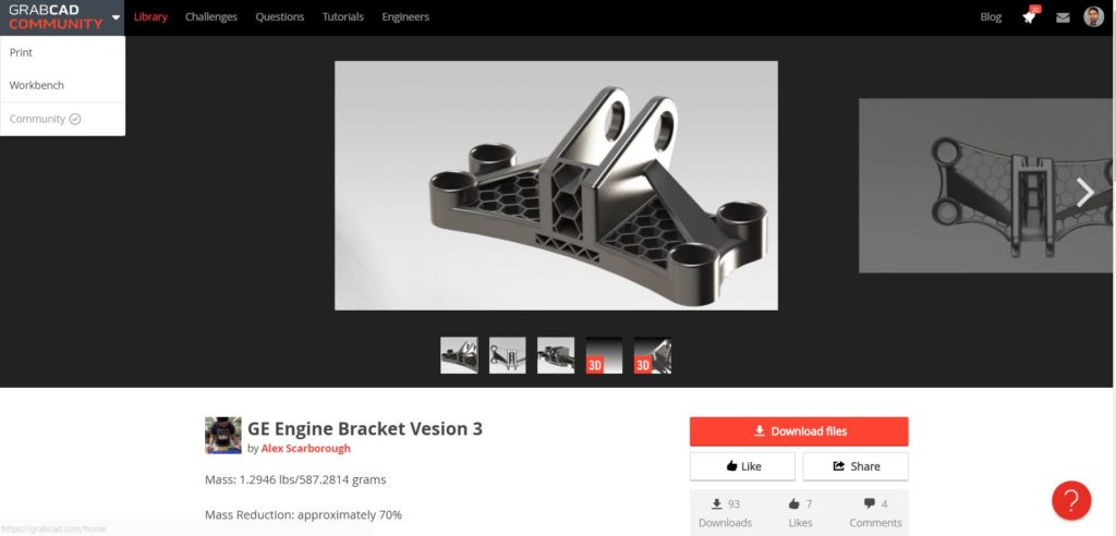
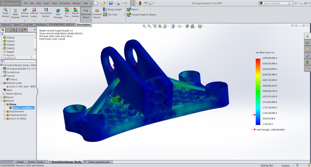
Run your FEA analysis to determine stress, displacement, or temperature. Your screen should look like this:
Usually, you’d want a bit more contrast in the printed models. adjust the results scale until the highest stress areas are bright red rather than green:
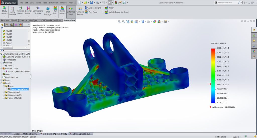
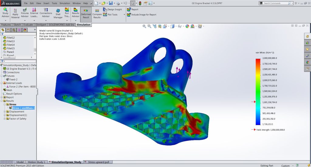
SOLIDWORKS Simulation is being used to do this particular FEA, the steps should be relatively similar in any modern package. Next comes the most significant step, which is exporting results in a way 3D printers can read them.
Step 2: Export Results As VRML
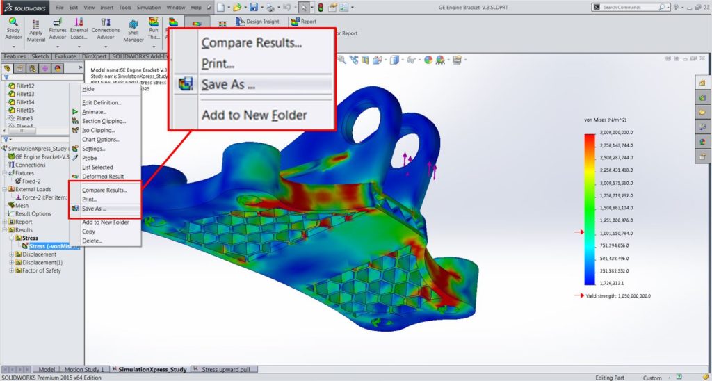
When using SOLIDWORKS, one way to export FEA results is by right-clicking on the resulting graph and choosing the “Save As” option:
The “Save As” choice brings up this screen, so ensure you’ve chosen VRML as your choice of format:
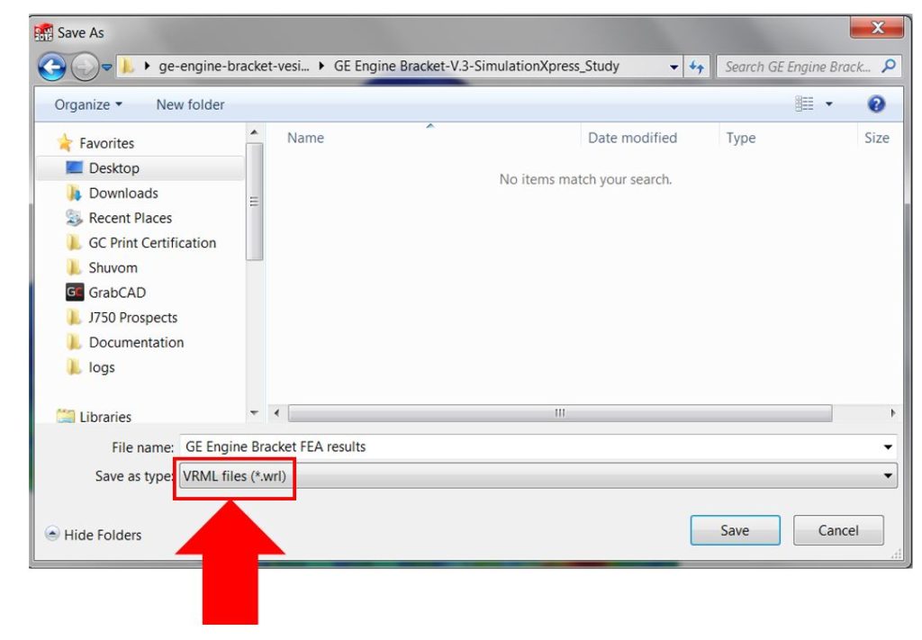
VRML is a format that was originally produced for Virtual Reality programs. However, this has also been used for sharing 3D files with full colour and texture. When your VRML is ready, layout the tray.
Step 3: Lay Out Tray In GrabCAD Print
GrabCAD Print is a 3D printing preparation tool; a tool of which can import STL files that don’t retain their colour, native CAD files, that retain the block colour assigned to their CAD system, and VRML, which usually retains full colour and textures when imported.
After importing the bracket VRML into GrabCAD Print and choosing Stratasys J750 for our choice of printer, our tray looks like this:
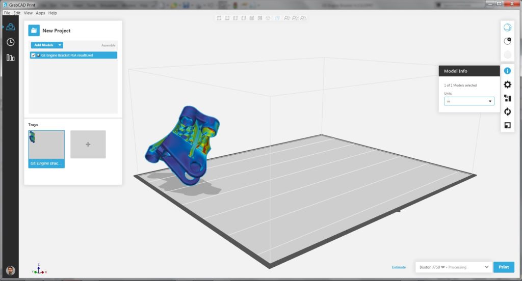
NOTE: Units of the VRML file could potentially not match the default units in your GrabCAD Print install. The first bracket came in 1000 times too small until the import units were changed to meters.
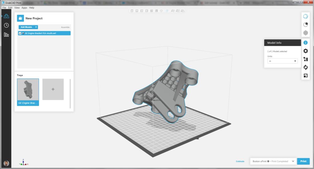
NOTE: If you have an FDM printer selected or even one which doesn’t have a full-colour range, your preview will look different. Here is the same bracket on a uPrint tray:
NOTE: If you’ve had your model in a “deformed state” during step 2 in SOLIDWORKS, those deformations will show up in the VRML. An example would be how the formerly flat bottom of the bracket is now bent upwards, which shouldn’t print. In order to fix this, you’d have to redo step 2 with deformations off.
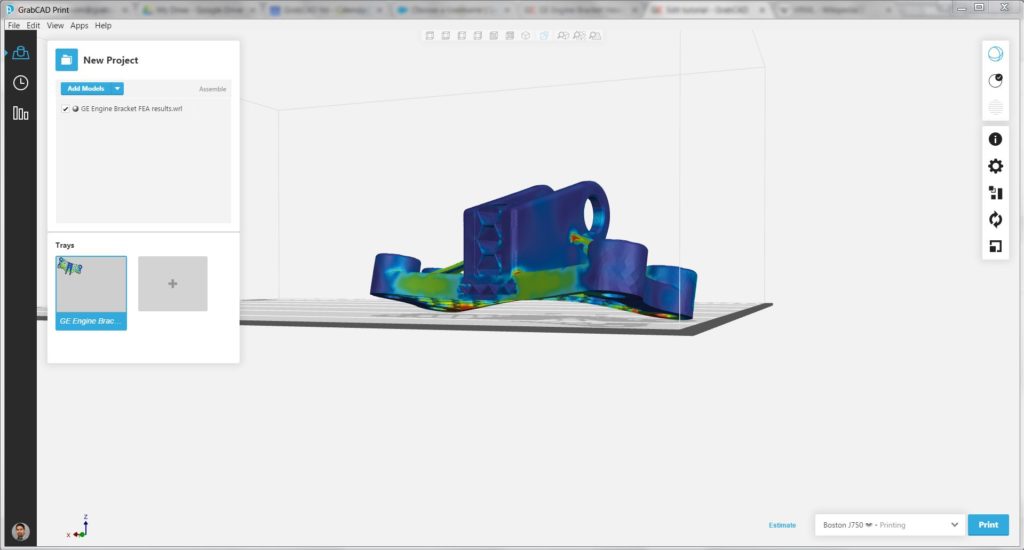
Assuming the J750 is the printer of your choice, your VRML would be exported in the non-deformed state, and if your scale is correct, your bracket on the tray should look like this after re-orientation.
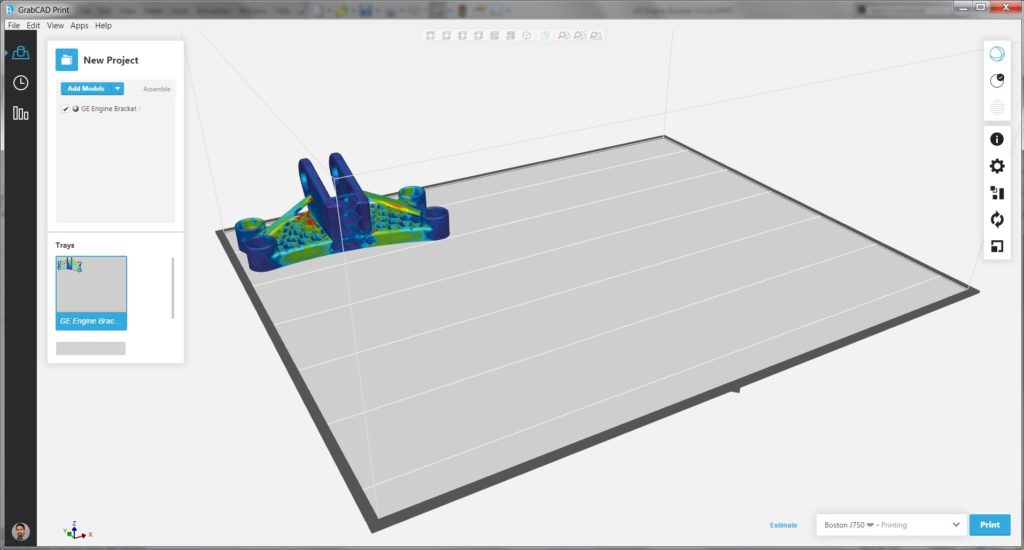
Scale the model or make duplicates at this time if you wish to do so because the last step is to hit the print button on the lower right.
Step 4: Print Your Model
That GE bracket can take 10-15 hours to print. This depends on the scale and print quality used. After coming back the next morning and after cleaning off supports, this was the final result:
