-
Introduction
As with other 3D printing technologies, there are recommendations to follow when designing for HP Multi Jet Fusion technology to ensure parts and features are printed to specification.
-
Wall Thickness
Generally, the minimum recommended wall thickness is 0.3 mm for short walls oriented in the XY plane and 0.5 mm for short walls oriented in the Z direction.
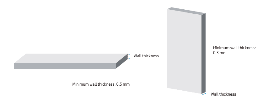
Fig. 1 Minimum wall thickness -
Cantilevers
When printing a cantilever, the minimum wall thickness depends on the aspect ratio, which is the length divided by the width. For a cantilever with a width of less than 1 mm, the aspect ratio should be less than 1. There are no specific recommendations for widths of 1 mm or larger. For parts with a high aspect ratio, it is recommended to increase the wall thickness or to add ribs or fillets to reinforce the part.
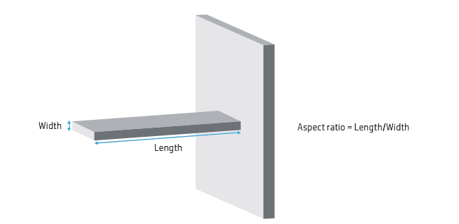
Fig.2 Cantilevers -
Connecting parts
Sometimes a pair of printed parts must fit together to form the final application. To ensure correct assembly, the minimum gap between the interface areas of these parts should be at least 0.4 mm (±0.2 mm of tolerance for each part).
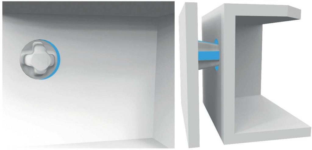
Fig.3 Minimum gap between connecting parts -
Moving parts
Generally, spacing and clearance between faces of printed assemblies should be a minimum of 0.7 mm.
Parts with walls with a minimum thickness of 30 mm should have a larger gap between each side to ensure proper performance.
For parts with walls that are thinner than 3 mm, the clearance between parts printed as assemblies can be as low as 0.3 mm, but this entirely depends on the design, and iterations with the manufacturer may be necessary to ensure quality performance.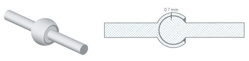
Fig. 4 Minimum gap between moving parts -
Thin and long parts
Thin and long parts are susceptible to non-uniform cooling, which may cause uneven shrinkage along the printed part, distorting in a particular direction that deviates from the nominal shape.
As a rule of thumb, any part with an aspect ratio—length vs. width—higher than 10:1, or any part with an abrupt change in its cross-section or a predominantly long and thin curved segment is susceptible to exhibiting warpage as shown in the image below: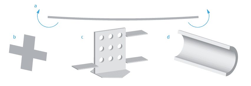
Fig.5 Part categories susceptible to shrinkage-induced warpage (a) include: thin and long parts (b), parts with abrupt changes in cross-sections (c), and thin curved surfaces (d) To minimize the possibility of this deformation, there are several recommendations to keep in mind when designing the part:
- increase the thickness of long walls to reduce their aspect ratios
- avoid ridges and ribs on large, flat areas
- re-design parts with high potential stress and smoothen their cross-section transitions
- lighten the parts by hollowing them or by adding internal lattices.
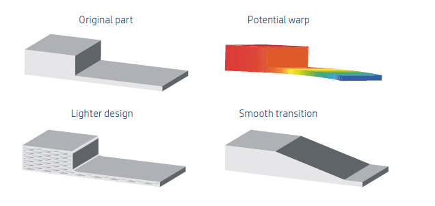
Fig. 6 Warpage mitigation strategies -
Design Optimization Strategies: Solid part or structural fill
HP Multi Jet Fusion technology allows for printing topology-optimized, generative designs or even small lattice structures. This kind of design allows for the creation of thinner sections, which accumulate and re-radiate less heat, improving the dimensional accuracy and general look and feel of the parts.
It also helps to reduce the weight of the part, the quantity of material, and the fluid agent used compared with fully solid designs, which not only reduces the cost of the part but also helps reduce the operating cost in very weight-sensitive applications.Hallow parts
This design optimization strategy involves hollowing the model through an automatic process. (Professional software such as SolidWorks, Materialise Magics with Materialise Build Processor for HP Multi Jet Fusion technology, and Autodesk® Netfabb® have this built in.)
The minimum recommended wall thickness is 2 mm, but higher mechanical properties are achieved with thicker walls. The optimum choice is dependent upon the application.
Once the model has been printed, drain holes can be implemented in the hollow part to remove the trapped unfused powder. Otherwise, the trapped unfused powder can remain within the part, resulting in heavier and more resistant parts than the fully hollow option. While the part is still light, it is weaker than the non-hollowed version. The difference in weight stems from the different densities of fused and unfused material.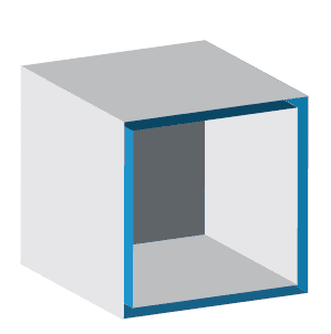
Fig. 7 Example of hallow part Lattice structure
This design optimization strategy involves hollowing a part and replacing the internal solid mass with a lattice structure that provides mechanical integrity via the collective action of many rigid cells while still noticeably reducing the part’s mass and cost.
This re-design is also a fast process that can be automated with professional software such as Materialise Magics or nTopology.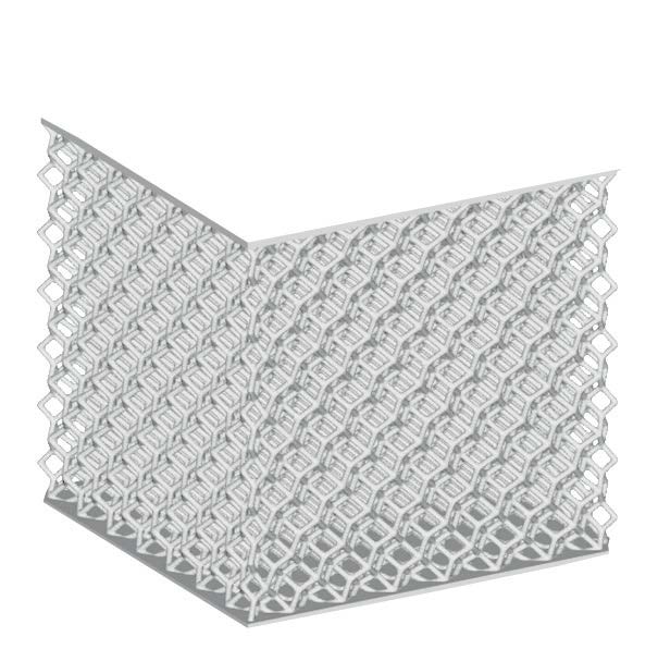
Fig. 8 Example of a lattice structure Topology Optimization
Topology optimization is a finite element method (FEM)–based process that finds the best distribution of material given an optimization goal and a set of constraints. Typical optimization goals are mass reduction and creating specific mechanical properties. This process requires the designer to know the part’s function and load distribution in depth but provides the most optimized method of reducing weight and cost from the original design.
HP part optimized by Autodesk with Netfab
- Company
- Products
- Manufacturing Services
- Resources
- Why Silicone 3D Printing?
- Fuse 1 | SLS Design Guidelines
- Technical Support, Repairs for 3D Printing, CNC Milling, 3D Scanning
- Terms and Conditions – Annual Maintenance Contract Proto3000
- Billable Technical Support & Repair Services
- Proto3000 Webinar Series
Skip to content

HP Multi Jet Fusion (MJF) 3D Printing Design Guidelines
Best practices and considerations for optimizing designs for the HP Multi Jet Fusion 3D Printing Process
3D Printing Services
- Additive Manufacturing Services
- 3D Printing Technologies
- Finishing and Assembly
- Digital Light Processing (DLP) Design Guidelines
- MJF Design Guidelines
- PolyJet 3D Printing Design Guidelines
- FDM Design Guidelines
- SLA 3D Printing Design Guidelines
- SLS Design Guidelines
- BMD Design Guidelines
- Metal Binder Jetting Design Guidelines
- DMLS Design Guidelines