-
Introduction
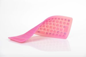
PolyJet, otherwise known as Material Jetting, is known as one of the most accurate 3D printing technologies. It produces high detail parts with smooth finishes. PolyJet is regularly used to produce visual prototypes.
The lack of heat during this process calls for more design freedom. This comes with fewer design rules outside of minimum feature sizes. Standard design recommendations allow a decent amount of room for support material removal.
Through following these PolyJet 3D printing design guidelines your parts should come out as intended, but for additional questions and complex problems be sure to reach out to a member of our engineering team. This video gives a great general overview about PolyJet 3D printing technology and what it can be used for.
-
Applications
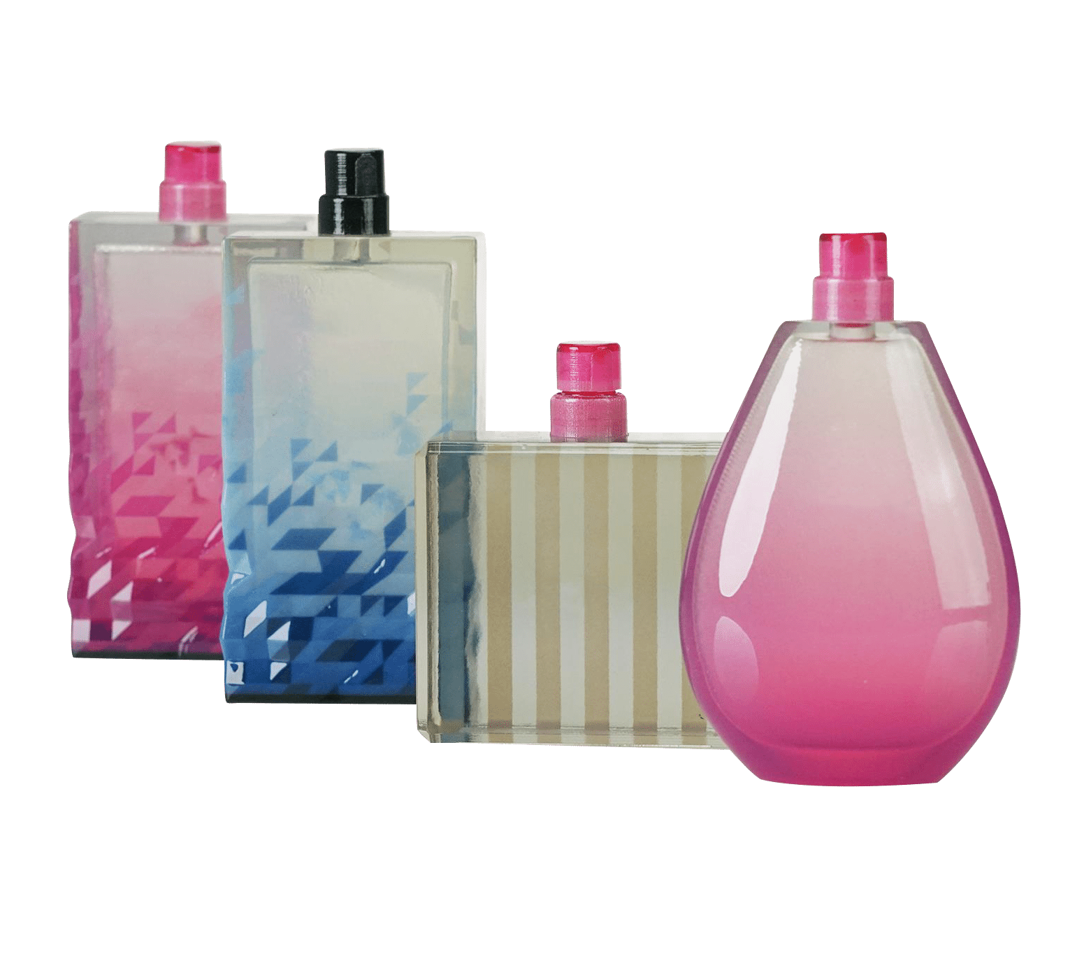
PolyJet is essential when the user wants to design prototypes or models in full colour, which includes gradients and graphic textures. Two file formats can be used when working with PolyJet parts. Those are STL (shell-based format) or VRML (virtual reality modeling language). Using either STL or VRML depends on the part’s colour and transparency needs.
If you’re model requires clear material or colour tinted transparencies, STL is used. Using clear material can showcase interior anatomical features in medical models. RGD colour codes from the PolyJet colour Guide are used to assign colour and transparency. When the model is divided into shells, designers have the ability to select the colours and transparency of each shell. The PolyJet Colour Guide specifies this as well as checkered pattern that signifies transparency. As the assembly is built as one whole part, a variety of sections if the assembly will have the same colour code applied and submitted as a single STL.
When dealing with parts that are designed with opaque colours or a coloured graphic texture, the user will want to use VRML. If the designer is looking to provide the capability to apply texture to a model, using (.wrl) standard format is necessary.
-
Multi-Material Integration
Multi-Material Integration
If you’re looking to achieve printing multiple materials at once, material jetting technology is the only way to go. The functionality of multi-material printing can be used in three different ways.- Mixed Trays
Uses the same build platform to produce different materials - Mixed Parts
Produced by multiple materials
Removes the need for assembly components (this increases production speed)
Realstic designs are made when used in conjunction with full coloured printing - Digital Materials
Digital materials occur when two or three resins join together (in specific concentrations and microstructures) to create a composite material with hybrid attributes
Flexible + rigid materials means there’s a possibility to produce parts which have exact properties
- Mixed Trays
-
Multi-Material Design
Digital materials and mixed tray don’t need the extra work, besides the designation of the material on a part basis. When working with mixed part prints, it is recommended to separate design into discrete bodies/shells. This assigns each body to a different material.
-
Support Structures and Part Orientation
Escape Holes
More times than not, escape holes are not needed as they generally don’t help out when removing support material. This is because the support material is being printed as a solid, compared to SLS or SLA which material that is removed is a liquid or powder.Support Removal
To avoid damaging an intricate part or fine details on a model, steer clear from manually removing support with a pressurized water can. Manual support removal with smaller tools allow finer features to be cleaned properly.Finishes
You may want to consider using the glossy finish vs. matte finish when stronger features are required. Glossy features are often stronger when defining a part surface finish. -
Technical Specifications
Maximum Accuracy 0.1-0.3 mm Part Dimensions (single build) 490 x 390 x 200 mm (19.3 x 15.35 x 7.9 in)
Layer Thickness 27 microns (0.00106 in)
Layer Resolution 16 microns or 0.016 mm/0.0006 in X/Y resolution = 0.0017
Standard tolerances ± 0.005” ± 0.001”/”
Shore Hardness Ranges 27A-95A Finishes Matte/glossy 

Consider the following guidelines when working with PolyJet materials.
Feature Description Wall thickness Thickness = distance between part surface and opposite sheer surface. Minimum wall thickness = 1mm.
Dimensional Accuracy PolyJet has the highest dimensional accuracy. Standard accuracy of materials range from 0.1-0.3 mm. This depends on the geometry, part orientation and print size.
Connecting/Moving Parts Water-soluble material in PolyJet allows for interlocking and moving parts Minimum clearance on parts that are printed together is 0.4 mm
Embossed/Engraved Details 0.5 mm high and wide Supported Walls 1 mm Unsupported Walls 1 mm Minimum Features 0.5 mm Holes 0.05 mm diameter Pin Diameter 0.5 mm
- Company
- Products
- Manufacturing Services
- Resources
- Why Silicone 3D Printing?
- Fuse 1 | SLS Design Guidelines
- Technical Support, Repairs for 3D Printing, CNC Milling, 3D Scanning
- Terms and Conditions – Annual Maintenance Contract Proto3000
- Billable Technical Support & Repair Services
- Proto3000 Webinar Series
Skip to content

PolyJet 3D Printing Design Guidelines
Prepare your designs for 3D printing with a PolyJet Technology process with these guidelines
3D Printing Services
- Additive Manufacturing Services
- 3D Printing Technologies
- Materials
- Finishing and Assembly
- Digital Light Processing (DLP) Design Guidelines
- MJF Design Guidelines
- PolyJet 3D Printing Design Guidelines
- FDM Design Guidelines
- SLA 3D Printing Design Guidelines
- SLS Design Guidelines
- BMD Design Guidelines
- Metal Binder Jetting Design Guidelines
- DMLS Design Guidelines