-
Introduction
SLS (Selective Laser Sintering) is a powdered based fusion technology which requires a laser beam to sinter polymer powder, building parts layer by layer. Powder located in the overflow bin is heated at high temperatures, where a recoating blade deposits an extremely thin layer of the powdered material (0.1 mm) onto the build platform. The building platform then scans an entire cross-section which moves the platform down one layer thickness in height. Powder that has been unsintered will stay in the same spot to support subsequent layers getting rid of the need for support structures. The recoating blade adds another layer of powder on top of the layer that has already been scanned. The laser beam then sinters the cross-section part onto the previously solidified cross-section. This operation is repeated until parts a fully completed. SLS is necessary for users who are looking for a solution in producing functional products with complex geometries This technology has little to no restrictions compared to other 3D printing technologies.
Through following these Selective Laser Sintering (SLS) 3D printing design guidelines your parts should come out as intended, but for additional questions and complex problems be sure to reach out to a member of our engineering team.
-
Feature Designs
When designing for SLS, consider the following recommendations to improve the overall quality and finish of your product.
Feature Description Wall thickness 0.7 mm (PA12) – 2.0 mm (carbon filled polyamide) Hole Size Holes should exceed a 1.5 mm diameter Escape Holes Minimum of 3.5 mm diameter Escape holes are necessary to remove unsintered powder
Minimum Feature Size Minimum size recommended = 0.8 mm Embossed details Minimum height is 1 mm Engraved Details Minimum depth of 1 mm Text Assure the following rules apply for text readability Minimum font height = 2 mm (font size 14) for every direction
Sans serif font should be utilized for readability
Connecting/Moving Parts 0.3 mm = moving parts 0.1 mm = connections
Supported Walls 0.7 mm Tolerances ± 0.3 mm or ± 0.05 mm/mm (whichever is greater) -
Materials
Materials that are offered with SLS are almost endless. A majority of them are polyamide based, which means it is synthetic thermoplastic polymers. This is also known as nylon. Below presents SLS’s most frequently used materials being printed and their benefits/properties.
Material Benefits PA12 Good dimensional stability Good wear resistance
High chemical resistance
Mechanical properties that can be compared to injection moulded polyamide
PEBA (TPA) Rubber-like Strong
Flexible
Alumide (Polyamide filled with aluminium) High stiffness Post-processing abilities
Carbon filled polyamide High stiffness High strength
Glass filled polyamide High stiffness Wear resistance
PA11 High impact resistance Elongation at break
Environmentally friendly
PEEK Well mechanical properties High temperature resistance
-
Applications
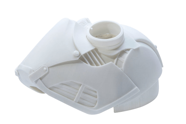
SLS applications allow functional prototyping or large production parts in taxing environments. Prototypes with mechanical properties similar to injection-molded parts are used, as well as lightweight designs in complex lattice structures. Certain design applications for SLS below will mark several instructions that will ensure a better quality SLS part.
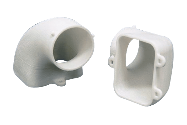
Application Design Axles Nylon provides smooth low friction mechanism for low load and velocity applications Surface clearance of 0.3 mm is recommended for running axles
Powder must be removed to ensure smooth running shaft
Escape holes with the minimum size of 3.5 mm diameter must be included wherever possible
2 mm between the running shaft axle and clearance shaft hole is required to allow for powder removal
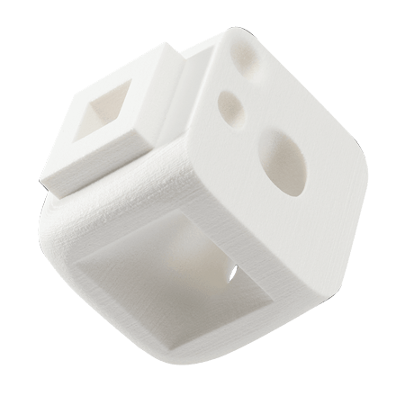
Integrated Hinges Works well with SLS nylon when designed accurately Pocket the shape of a trapezoid accepts a semi-spherical ball
This allows for low friction and decent stability
0.2 mm of space between the sphere and pocket is suggested with 0.3 mm clearance between every other gap
Tanks SLS nylon provides chemical resistance Executed in custom tank design
Anything greater than 1 mm is required for the wall thickness
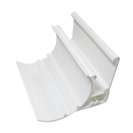
Threads SLS produces rough surfaces when increased friction connects the threaded SLS parts together Living Hinges SLS is a printing method that produces functional living hinges Anneal the hinges by heating it up and flexing the hinge back and forth
Hinges should be 0.3-0.8 mm thick and minimum 5 mm in length
-
SLS VS. Injection Molding
Compared to injection molding, SLS parts are often used as prototypes to determine the following three forms of design:
- Function
- Form
- Fit
Later, these designs will be manufactured using injection molding. The main differences between SLS and injection molding are as followed.
Injection Molding SLS Injection molding must be removed from a die Can not produce undercuts, negative drafts or interior features
No removal of die required Can easily conduct undercuts, negative drafts and interior features
Costly Terminates need for costly tooling More affordable for a small series production
Has the ability to produce sharp edges and exact corners Can only produce parts that include a radius of ±0.4 mm at all corners and edges Keep in mind that a radius of 0.4 mm on a design will be printed as 0.4 mm
Stress relief is not offered Natural radius offers some stress relief Areas of concern require a larger radius than 2 mm
-
Limitations
Product Size The size of a part being printed is limited by the size of the nylon containers used in SLS machines Average build volumes = 300 mm x 300 mm x 300 mm
Larger machines offer build volume of 700 mm x 380 mm x 580 mm
Consistency Because there are so many layers within printing SLS parts, variations between products may occur within the dimensions and surface quality Post processing steps are done manually
Minor variations may occur such as small colour or coating variations
Surface Finish Grainy finish Post processing recommended
- Company
- Products
- Manufacturing Services
- Resources
- Why Silicone 3D Printing?
- Fuse 1 | SLS Design Guidelines
- Technical Support, Repairs for 3D Printing, CNC Milling, 3D Scanning
- Terms and Conditions – Annual Maintenance Contract Proto3000
- Billable Technical Support & Repair Services
- Proto3000 Webinar Series
Skip to content

Selective Laser Sintering (SLS)
Selective Laser Sintering (SLS)
3D Printing Design Guidelines
Prepare your designs for 3D printing with the SLS Technology process using these guidelines
3D Printing Services
- Additive Manufacturing Services
- 3D Printing Technologies
- Finishing and Assembly
- Digital Light Processing (DLP) Design Guidelines
- MJF Design Guidelines
- PolyJet 3D Printing Design Guidelines
- FDM Design Guidelines
- SLA 3D Printing Design Guidelines
- SLS Design Guidelines
- BMD Design Guidelines
- Metal Binder Jetting Design Guidelines
- DMLS Design Guidelines