-
Quick Reference
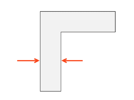
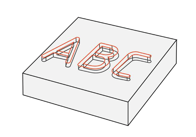
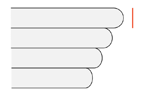
Minimum Feature Size Wall Thickness Character Height Self-Supporting Horizontal Hole Self-Supporting Angle Self-Supporting Overhang Self Supporting Bridge Recommended minimum: 0.50 mm Recommended minimum: 1.50 mm Absolut minimum: 0.20 mm
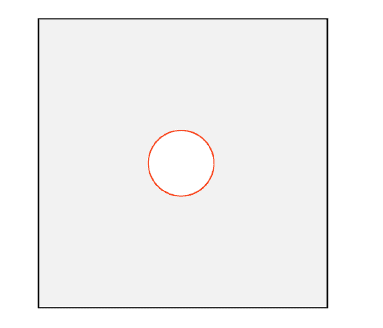
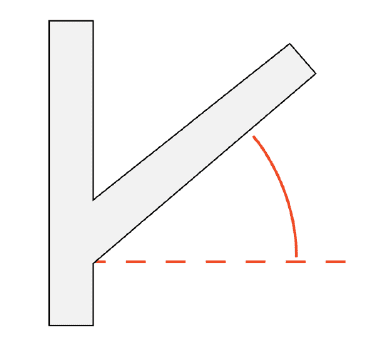
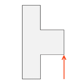
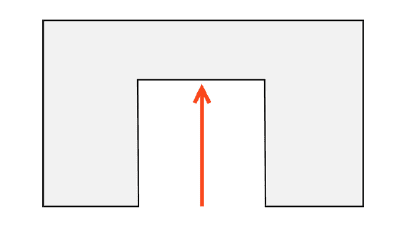
Raised (positive), min.: 2.0 mm horizontal surface, 3.0 mm vertical surface. Recommended maximum: 25.0 mm diameter. Recommended maximum: 30° from horizontal Recommended maximum: 1.0 – 2.0 mm Maximum recommended: 5.0 mm Absolut minimum: 3.0 – 5.0 voxels Recommended maximum: 12.0 mm+ Recessed (negative), min.: 1.0 mm horizontal & vertical surface. Absolute maximum: 15° from horizontal 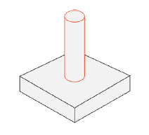
-
Introduction
The Envision One features patented cDLM (continuous digital light manufacturing) technology, enabling continuous printing. The Envision One delivers exceptional speed, print resolution, surface finish, and part properties with little to no delay between layers.
The P4K is the opposite of other, one-size-fits-all 3D printing solutions. With various models available, users can choose their optical configuration based on part size, feature-size requirements and throughput and tailor a solution that best suits their needs. With resolutions of between 23µm-90µm on the X and Y axes, the P4K can easily produce detailed parts of various sizes.Introducing the D4K, the highest resolution professional-grade desktop 3D printer. In addition to having the fastest speed for a standard DLP printer, the D4K from ETEC delivers extremely accurate parts with the finest detail available. Brought to you by the original inventors of DLP 3D printing technology.
With ETEC’s family of hard plastics, you get the dimensional accuracy, surface quality and speed of the world’s leading DLP printing systems, along with material properties rivalling leading thermoplastic materials (e.g. ABS, PA12, ULTEM, and TPU).The below design guidelines have been developed for the following 3D printers:
- Envision One cDLM series (including Envision One cDLM XL)
- P4K series (including P4K 90, P4K 75, P4K 62, P4K 35)
- D4K
-
Build Envelope
The build envelope is the maximum available printing space on a 3D printer. It determines how large of an object the printer can build.
The size of the build envelope depends on the size of the projector, the distance between the projector and the material tray, and the maximum height of the build platform on the Z axis.3D Printer D4K P4K 90 P4K 75 P4K 62 P4K 35 EnvisionOne, cDLM series X-axis 140 mm 223 mm 192 mm 160 mm 95 mm 180 mm Y-axis 83 mm 141.5 mm 120 mm 100 mm 56 mm 101 mm Z-axis 110 mm 220 mm 220 mm 220 mm 200 mm 175 mm (320 mm XL) Pixel size 50 μm 90 μm 75 μm 62 μm 35 μm 93 μm Minimum Part Size
There is no minimum part size for the Envision One cDLM, P4K, or D4K. TIP: Printed parts under 5.0 x 5.0 x 5.0 mm may be hard to handle during post-processing.
 -
Feature size
The minimum resolvable feature size is dependent on:
- the specific printer
- the material and
- the feature geometry.
To better understand the achievability of small features, it is useful to think about voxels.
Voxels
A voxel is a three-dimensional pixel.
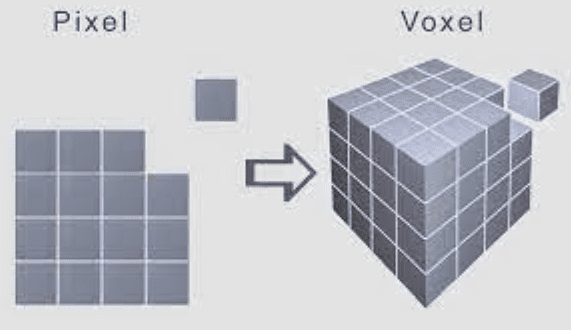
The dimensions of a voxel are based on:
- the native pixel size of the printer in the X and Y coordinates,
- and the layer height in the X and Z or Y and Z coordinates.
Layer Height
Layer height is the thickness of the material cured in each layer during a print job and is material-dependent.
3D Printer D4K P4K 90 P4K 75 P4K 62 P4K 35 EnvisionOne Pixel Size 50 μm 90 μm 75 μm 62 μm 35 μm 93 μm Layer Height 25-150 μm 25-150 μm 25-150 μm 25-150 μm 25-150 μm 50-150 μm Minimum Feature Size:
The minimum feature size must be at least three times the voxel size of the printer.
❖Example: The D4K has a 50 μm voxel size and a minimum resolvable feature size of 3.0 pixels or 150 μm.
For horizontal features, ETEC® recommends a minimum resolvable feature size of five times the layer height.
❖Example: E-RigidForm material has a 100 μm layer height and a minimum resolvable horizontal feature size of 500 μm.
-
Wall Thickness
Part wall thicknesses from as thin as 2.0 mm to over 10.0 mm are printable without special considerations. The printability of wall thicknesses under 2.0 mm depends upon:
- geometry
- orientation
- and material.

Freestanding walls as thin as 0.20 mm can be printed when correctly oriented and reasonably sized.
Minimum Wall Thickness
The minimum recommended wall thickness is 0.50 – 1.0 mm, depending on the material and geometry.
-
Character Height
Minimum character height differs if:
- the text is raised or recessed, and
- the text is placed on a vertical or horizontal surface to the Z axis.

The recommended feature depth/height for text is 0.50 mm.
❖NOTE: Testing was performed with both serif and sans-serif fonts. Sans-serif fonts are slightly more legible at the minimum size.
Minimum character height
Raised (Positive) Recessed (Negative) Parallel 2.0 mm 1.0 mm Perpendicular 3.0 mm 1.0 mm -
Self-Supporting Features: Self-Supporting Horizontal Hole
Horizontal holes are built through a series of overhanging layers during printing. The overhang distance of each layer increases slightly as the hole is built.
The maximum overhang for small to medium holes is less than the recommended maximum support-free printing.
Holes as large as 25.0 mm can be printed without supports. Holes up to 75.0 mm can print without supports; however, some deformation can occur.
-
Self-Supporting Features: Self Supporting Angle
The maximum self-supporting angle is 30° from the horizontal. Angles as shallow as 15° may be printed without supports, but some deformation can occur.

-
Self-Supporting Features: Self Supporting Overhang
Overhanging features are printable without supports in some instances. Overhanging features within 1.0 – 2.0 mm are possible to print without supports.

Supports are recommended for overhanging features longer than 2.0 mm.

TIP: Fillets or chamfers can be utilized in the design process to help reduce the length of unsupported overhangs.
-
Self-Supporting Features: Self Supporting Bridge
Bridging features are geometries where a new layer of material connects a span between two areas. Bridges should be kept under a maximum length of 5.0 mm.

TIP: Chamfers and fillets can be utilized in the design process to reduce the effective bridging distance.

-
Venting and Draining
Resin flow must not be inhibited during the DLP and cDLM printing processes. Unvented and watertight volumes require special considerations.
A small drain/vent hole should be used to enable reliable and accurate printing.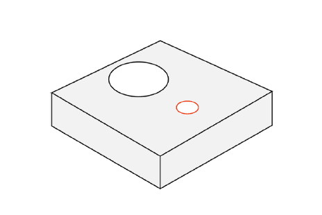
Vent holes should be around 1.0 mm in diameter. Smaller holes are possible, depending on the material, printer, and geometry.
Drain/vent holes larger than 1.0 mm may be used and sealed with a printed plug after post-processing.
Skip to content
Digital Light Processing (DLP) 3D Printing Design Guidelines
Best practices and considerations for optimizing designs for ETEC’s Digital Light Processing (DLP) 3D Printing Process