-
Overview
Application
An alternative method to traditional tool-making is offered with Fused Depositon Modeling (FDM). Some of these procedures have been applied to Type 1 (thick-wall) and Type 2 (thin wall) paper pulp molding processes. Proto3000 is here to guide you through this process. In this guide, you will learn how how FDM is used in paper pulp molding. If there’s something you don’t understand, do not hesitate to get into contact with our team. If you are looking for 3D printed paper pulp molds, you have them manufactured with our 3D printing service bureau.
Presently, no data on Type 3 (thermoformed fiber) processes
Success is common, but has not been attempted as of yet.Presently, no data on heat-press tooling or on-tool part drying
With proper FDM material selections and temperature management. Success may occur, but hasn’t been attempted.Tool Life
30,000 or more cycles are possible
Tool life depends on the part or tool configuration, processing parameters and cycle rates
When Is FDM Best Fit?
Production runs, low-volume prototype, bridge-to-production
Tools sizing: less than 3 feet (0.9 meters) in length
Only limitation is practicality of large tool constructions using available FDM Fortus systemsComplex shapes
Additive manufacturing advantages showcase best when the part and tool have organic shapes and many features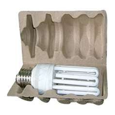

-
Process Overview
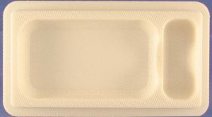
The following steps are involved in the traditional paper pulp molding process:
Manufacturing pulp molding tool
Machine metal billet to net-shape
Drill pattern of vacuum holes
Cut, place and form screen over molding surfacesManufacture transfer tool (Type 2)
Machine metal billet to shape
Drill several vacuum channelsMount your tool on a vacuum plate
Ensure you manufacture paper pulp parts
Immerse tool is paper slurry
Pull vacuum in order to draw paper fibers against the screen
Eject the part into transfer tool and transport to the conveyor
Use the oven to dry the part
Modifications
In order to add FDM tooling into the paper molding process, there are necessary adjustments, alterations and substitutions that need to be made to the following steps:
Tools design
Although the CAD model is broken down to two or more discrete files, tool design remains unchangedManufacturing pulp molding tool
Machined tool is replaced by FDMManufacturing transfer tool (optional)
FDM replaces machined transfer toolOther processes are unchanged
-
CAD File Adjustment
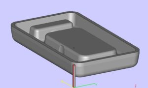
CAD Model
Use a 3D CAD model for the paper pulp mold. Modification is unnecessary although the design has the potential to be altered to leverage the additive manufacturing process.
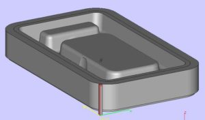
Segment CAD Model
In order to have the file processing procedures in Insight accomodated, it’s important to create a CAD model for each of the three following regions of the tool.
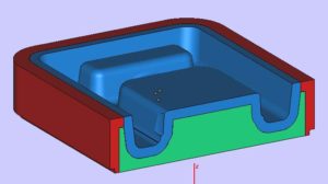
Solid: Solid outer boundary of the tool Screen: Molding the surface of the tool that forms the paper pulp Mesh: The back-fill area behind the screen - Structural only
- No vacuum drawn through
- Vacuum drawn through this surface to draw fibers against the mold
- Structural integrity provides chamber region that delivers vacuum to the screen
- Prevents molding surfaces from flexing inward
- This can be optional for many Type 2 molds that come with low compressive forces during vacuum draw
- This is vital for the thicker walled Type 1 molds
Registration Feature To CAD Model Is Added
Using the native CAD application, open the CAD file for the mold. Next, construct a reference block using the origin (0, 0, 0). You will be able to find the reference block in front of, as well as to the left of the CAD model. Keep in mind that it shouldn’t impinge on the model. When referencing orientation (mounting surfaces vs. molding surfaces), it’s best to suggest a distinguishing mark or feature on the top of the reference block, The reference block dimensions should be as followed:
X/Y: About 0.25 in. (6.4 mm)
Z: Height of the tool + 0.10 in. (2.5 mm)
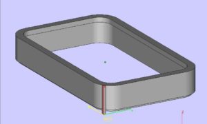
Create Solid Component
From the model, subtract all molding surfaces and the materials below. This will leave a solid “frame” around the boundary of the tool. Then, save the file as (solid_file). Export the STL.
Create Screen Component
Open tool_original, then import and subtract solid_file. Do not subtract the reference block. Then, make 0.25 in. (3.18 mm) shell. Offset the outer surface towards the interior of the tool and subtract all material below the offset. Moving forward, save the file as screen_file and then export the STL.
Create Mesh Component
After opening tool_original, import and subtract solid_file and screen_file, but do not subtract the reference block. Furthermore, create a 0.001-inch (0.025 mm) clearance from the solid and screen components. Lastly, save the file as mesh_file and export the STL.
-
File Preparation using Insight
A paper pulp mold is required to havea good vacuum flow while minimizing clogging with paper fibers. In order for this to be achievable, process the STLs in Insight. This creates an FDM tool with goof air flow with tight pores and smooth surfaces.
Using this procedure uses a custom group library created specifically for paper pulp molding (Paper Pulp T16). This is now available under the ‘Import’ option in the ‘Custom groups’ function.
All file preparation steps must be complete in Insight application
Keep in mind the following process parameters can possibly be adjusted to optimize operational performance. Some adjustments could be required on a feature level.
Step 1: Process solid component
Open solid_file.stl
Slice the file
Save as solid_file.sjb and close the fileStep 2: Process the mesh component
Open mesh_file.stl
Slice the file
Import Paper PulpT16 (Toolpaths > Custom groups > Import)
Select all layers and add them to the internal mesh custom group.Note: This custom group produces an open, lattice-like structure that provides compressive strength without diminishing vacuum flow. Toolpath parameters also include:
No contours
Thick rasters (0.028 in./0.71 mm)
Air gap between rasters (0.150 in./3.81 mm)
Start angle (22.5″)
Delta angle (60″)Possible adjustments include:
Start angle
Layer between delta
Adjust the Start angle, at a feature level in order to avoid air flow blockage. Adjust the layer between delta to avoid having the same raster angle at the interface between the mesh and screen. Save as mesh_file.sjb and close the file.Step 3: Process screen component
The screen tool is the most critical step. It requires porosity while providing a smooth surface finish. This is possible by alternating the toolpaths for slices, one without a Perimeter and large Raster Gap. This allows s,all fibers to penetrate the surface and the large Raster Gaps will allow the small fibers to be drawn through the tool and back through the system- Open screen_file.stl
- Slice the file
- Import Paper Pulp T16 (Toolpaths > Custom groups >Import)
- Apply the .01 raster gap_no perim group to the odd numbered layers
This cistom group creates a toolpath without an outer perimeter (contour) and small (0.010-inch/2.03 mm) raster air gaps. Besides the raster air gap, it’s identical to the toolpath for the internal mesh.
Toolpath parameters:
No contours
Thick rasters (0.020 in./0.51 mm)
Air gap between rasters (0.010 in./0.25 mm)
Start angle (22.5°)
Delta angle (60°)It’s best to apply the 0.8 raster gap with perim group to the even number of layers. This custom group creates a toolpath with an outer perimeter (contour) and karge (0.080-in./0.25 mm) raster air gaps.
Toolpath parameters:
Contours to depth (0.020 in. contour; 0.020 in. depth [0.51 mm])
Thick rasters (0.020 in./0.51 mm)
Air gap between rasters (0.080 in./2.03 mm)
Start angle (45°) which will vary with geometry
Delta angle (90°)Apply .005 raster gap with perim group to the up facing surfaces. This particular custom group creates a decently solid, top molding surface. It also has a small amount of porosity. This allows fibers to be drawn against the surface while optimizing surface finish,
Toolpath parameters:
Perimeters contours (0.020 in./0.51 mm)
Thick rasters (0.020 in./0.51 mm)
Air gap between rasters (0.005 in./0.13 mm)
Start angle (45°). This may vary with geometry
Delta angle (90°)Reviews
- It’s also quite important to review the slice below each up facing surface. If it’s part of the .08 raster gap with perim group, change it to the .01 raster gap_no perim group. A smoother, more upfacing surface is developed with the smaller raster gap of the .01 raster gap_no perim group. With the large raster gap of the .08 raster gap with perim group. The visible surface rasters can dip as they bridge the 0.050 in. (2.03 mm) gap.
- Reviewing the file to find slightly sloped surfaces (< 45 degrees from horizontal. When working with any feature with an angle of less than 45°, use curves that use the .08 raster gap with perim group. Change these to the gradual sloped surf group. A gradual slope may expose the raster pattern of the layer below. The surface finish of the molded part may be too rough if this layer has the large raster gap of the .08 raster gap with perim. The gradual sloped surf group uses a 0.025 in. (6.35 mm) raster gap. All other parameters remain unchanged. This is to produce a smoother molding surface.
- Select all curves that interface with the internal mesh group which use either .08 raster gap with perim, ir gradual sloped surf groups. Then, apply the screen interface/mesh open rasters group. At the interface between both the mesh and the screen, there should not be any blockage of airflow. Getting rid of the perimeter and enabling application to user-selected features allows the boundary between the two regions to be opened.
Toolpath parameters:
Similar to .08 raster gap with perim group with the following exceptions; perimeter set to none, and turn on (check box). Applu to selected features only
Save as screen_file.sjb and keep this file opened
Adjustments And Optimizations
In order to achieve vacuum flow, minimize clogging or alter surface finish. Adjustments may be made to the tool path parameter in each custom group. Consider those in the imported custom group library as baseline for further tuning.
Note: Part geometries could dictate adjustments to toolpaths. This most often occurs for large radii corners or amgles (XY plane) surfaces.
If the Raster Start angle of the toolpath is at all parallel to the screen surface, the raster turnaround will block airflow. In order to have a resolution, adjust the Start angle in the custom group or create a new custom group with a different Start angle.
Step 4:Combine Processed files
Combine mesh files
Slice > Combine slice curve files command: select the mesh_file.sjb
Set slice curve location. X= 0.0, Y = 0.0, Z= 0.0The three files are now aligned, now, select and delete the curves for the alignment features. Ensure you generate supports, the toolpaths, and save as tool_combined
-
Material Selection
All Fortus materials are suited for paper pulp molding. This includes:
ABS
ABSplus
ABS-M30
PC (Polycarbonate)
PC-ABS
PPSF
ULTEM 9085
Suggested Materials
ABS materials are recommended. This is because it comes with good performance characteristics, and good processing characteristics.
Caution
Surface of the tool flexing and molding could cause PC to crack. This can often happen if the optional internal mesh is not used.
-
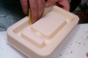
Post Processing
After the build, remove the supports from the tool which will now be prepared for operation.
Surface Smoothing
Sand the mold to the desired finish in order for production to run a smooth surface finish. Keep in mind that the solevent smoothing, including the use of a finishing touch smoothing station, is not an option. Solvent smoothing seals the surface which reduces the air flow through the tool.
Bonding Large Tools
Tools which go beyond that exceed the build time envelope of a Fortus system may be sectioned and bonded. For bonding, select from any of the techniques commonly used on FDM parts. This includes solvent epoxy bonding.
-
Molding
Process
No alterations are required to teh paper pulp molding process.
- Mount the FDM mold on the vacuum plate
- Begin molding the paper pulp parts. There’s no need to change any operatinf procedures or adjust any parameters.
Tool Cleaning
When the vacuum is insufficient, clean the paper fibers which are clogging the tool. Use a high-press water jet in order to blow the fibers out of the mold.
-
Success Factors
Process tool in Insight for good vacuum flow while maintaining
surface finish quality.
1. Sparse fill.
2. Porous walls.
3. Adjust toolpaths (custom groups).
4. Modify toolpath parameters for features that create
shut-offs.
5. Maintain structural strength.
6. Through material selection and/or use of optional internal mesh
- Company
- Products
- Manufacturing Services
- Resources
- Why Silicone 3D Printing?
- Fuse 1 | SLS Design Guidelines
- Technical Support, Repairs for 3D Printing, CNC Milling, 3D Scanning
- Terms and Conditions – Annual Maintenance Contract Proto3000
- Billable Technical Support & Repair Services
- Proto3000 Webinar Series
Skip to content

Technical Application Guide – Paper Pulp Molding with FDM 3D Printing
Home Technical Application Guide – Paper Pulp Molding with FDM 3D Printing