-
Overview
This step-by-step guide was designed as a resource to assist in medical 3D printing, and the process of going from DICOM files to 3D printed anatomical models. If you have complex requirements, are dealing with a new additive technology or imaging tool, or have any further questions about medical 3D printing, be sure to speak with one of our experts. If you are looking to have models produced with 3D printing technology, be sure to use our 3D printing services or click here for an instant quote.
Anatomical models have many medical applications; everything from patient-specific models used to plan and optimize surgical approaches, to sophisticated training simulations for physician education, to clinically relevant models to verify and confirm new medical devices. Because there is no tooling necessary for 3D printing, and because of the ability to reproduce complex structures with no added cost, it’s a much more natural match for such applications. Although, developing these models can often become a challenge due to the complexity and irregularity of human anatomy.
A beginners point would be to use data that is readily available in the form of patient imaging scans which are generated by non-invasive MRI, CT or 3D ultrasound testing. Given this information, model designers have the ability to recreate the complexity of any disease, abnormal anatomy or variation. An issue with using this approach would be to isolate the anatomy of interest, which is also referred to as segmentation. Then, it would be converted into a file format which is compatible by CAD and 3D printing software.
A variety of commercial, freeware and open-source solutions are accessible in order to perform these steps. The following further explains the approach using InVesalius (freeware) and Vitrea (commercial software) as examples, although the process has the ability to be replicated with many other solutions.
Segmentation software which is frequently used are listed below
InVesalius: free software to convert DICOM images to STL files. http://svn.softwarepublico.gov.br/trac/invesalius
OsiriX Lite: Free software to view and annotate DICOM files. http://www.osirix-viewer.com/osirix/osirix-md/download-osirix-lite/
Vitrea Advanced Visualization: Commercial software offered by Vital Images, a Toshiba company that automates many segmentation activities. http://www.toshiba-medical.eu/eu/healthcare-it/vital-solutions/vitreaadvanced/
Mimics inPrint: Commercial segmentation software with semi-automated tools and modules for orthopedics and cardiology. It is also used as pre-operative software for simulating and evaluating surgical treatment options and is a CE-marked medical device.
-
Obtaining DICOM Data
Digital Imaging and Communications in Medicine (DICOM) is the international standard, or requirement for medical imaging. This includes its storage, communication, transmission and file format and handling. DICOM is provided by request of Doctors. Modern medical imaging devices that are supported by DICOM standards will export readable files by all viewers and editing software shared in this document.
As the human body comes with many complexities, many imaging modalities are most commonly used towards patient care. Data representation and image intensity representation vary. Health care providers usually use one of the following modalities. This is based on the clinical question and availability. An example of this would be ultrasound equipment is more so available in smaller hospitals, so they may use it for initial screening and refer the patient to a larger center for an MRI test if further diagnostics are required.
3D printing creates mechanical structures, this makes it vital to comprehend what image intensity represents. DICOM output commonly provides a series of 2D images, otherwise known as slices, that are remodeled in 3D. This could either be for viewing on a screen or for physical reconstruction purposes.
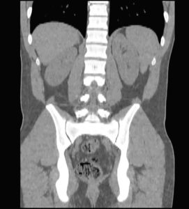
CT (Computed Tomography)
CT is known for using a series of X-rays that have been taken from various angles, only to later be reconstructed. The radio density of the tissue (the amount of X-ray that the tissue blocks) is represented by the pixel value. Where as the brightness represents a Hounsfield unit. Brighter areas are typically denser than darker areas. For instance, a bone is brighter than the surrounding connective tissues. Using this method is quick and can evaluate the structure of various tissues in the body. A negative side of this is the inability to differentiate structures that carry similar densities such as muscles and tendons.
CTA (Computed Tomography Angiography)
An injection is given to the patient with a contrast agent. The contrast agent will appear as a brighter region because of the representation of blood flow. Contrast agents traveling through the cardiovascular system showcases abnormalities like blood clots and aneurysms.
MRI (Magnetic Resonance Imaging)
A strong magnetic field is used during MRI’s to excite hydrogen atoms in the body, thus causing them to emit radio frequency detected by the scanner itself. Using this method is positive because hydrogen atoms exist within humans in large numbers. They specifically live in water and fat. This method also demonstrates s small differences between the soft structures in the body. MRI is most commonly known to test pathologies within the brain and muscle tissues. An advantage of this is that there is no exposure to harmful radiation.
MRA (Magnetic Resonance Angiography)
A contrast agent is injected into the patient when MRA is in use. Brighter areas will appear where blood flow is located. This technique is used to diagnose complications and issues such as strokes in the brain’s vascular system.
PET (Positron Emission Tomography)
In order to show where there are metabolically active regions, such as tumours, PET must be used to a biologically active molecule, typically a form of glucose.
3D Ultrasound
Different angles are sent into the body by using high-frequency sound waves. As they reflect back, the receiving device interprets the returned waves to produce a live 3D image of the internal organs. Although ultrasound images are good at showcasing the boundaries between liquid-filled organs and solid organs, it typically provides inferior resolution compared with other imaging techniques.
Modality Demonstrates Uses Advantage Disadvantage CT Density Bones/soft tissue Quick, high resolution Not useful for soft tissue/radiation exposure CTA Blood Flow Cardiovascular conditions Shows small blood vessels Doesn’t showcase surrounding tissue MRI Water and fat Brain and soft tissue, muscles No radiation with high resolution Doesn’t showcase surrounding tissue MRA Blood flow Cardiovascular conditions Shows small blood vessels Doesn’t showcase surrounding tissue PET Glucose intake Lymphatic conditions and tumours Shows activity in tumours Doesn’t showcase surrounding tissue 3D Ultrasound Boundary between organs Initial analysis, pregnancy related tests Cheap live images and no radiation Low resolution and doesn’t showcase internal structures -
Medical Viewers
There’s a numerous amount of software solutions available to display DICOM images. They vary from free-to-use open-source software to enterprise-level solutions using FDA clearance. The information given below will feature only a small subset of these solutions, which should be enough to cover most uses and interactions with medical imaging specialists.
Common software solutions
- OsiriX
OsiriX is a widely used DICOM viewer. It features a strong visualization engine that allows editing to be done. In order to download the free version, registration is necessary. The website uses free DICOM examples that could be used in other viewers - InVesalius
The Brazilian government supports this free software. It has the ability to create STL files using thresholding techniques and showcases a strong community with step-by-step guides. Although it performs good segmenting bone, it is less consistent when segmenting soft-tissue structures. - ITK-SNAP
This software is used to segment structure in 3D medical images. This stems from a product of collaboration between the universities of Pennsylvania and Utah. Their version was to create segmentation tool that would be easy to learn and use. This software is free and an open source, multi-platform tool. Using contour methods, semi-automated segmentation is provided. - Mimics By Materialise
Materialise, a 3D printing software company, designed Mimics which were made entirely for medical image processing. This is considered the infustry standard among large medical centers. It also features a strong segmentation and STL-creation engine - Mimics InPrint
Mimics InPrint is ideal if you’re looking for a simpler version of Mimics. It’s targeted to enable doctors to create 3D models with much better ease and speed. Some features associated with Mimics InPrint are thresholding and active contour segmentation modules - Vital Vitrea
Vitrea is a medical diagnostic system that allows the processing, review, analysis, communication and media interchange of multi-dimensional digital images from a variety of imaging devices. This system provides the ability to review digital images from original DICOM data for multiple modalities.
Software For Viewing DICOM Images
Name DICOM Import 3D Visualization STL Creation STL Fixng STL Editing FDA Clearance Thresholding Auto Segmentation Free OsiriX X X X InVesalius X X X X X X X ITK SNAP X X X X X X Mimics X X X X X X X X Mimics InPrint X X X X X X X X Vitrea X X X X X X Seg3D X X X X X X 3DSlicer X X X X X DeVIDE X X X X X X TurtleSeg X X X Segmentation Explained
Data must be segmented because medical imaging techniques show the entire body, including the surrounding tissues. Undesired data is then removed and the relevant portions remain.There are many techniques that can succeed at this. The following guide shows two primary methods that could potentially be experimented with while using free tools.
Additive manufacturing requires exporting one or more closed surface as an STL assembly. Discarding surrounding data and marking relevant data gets this done. Two techniques mentioned below vary in their approach to segmentation, and are commonly used techniques.
Segmentation techniques
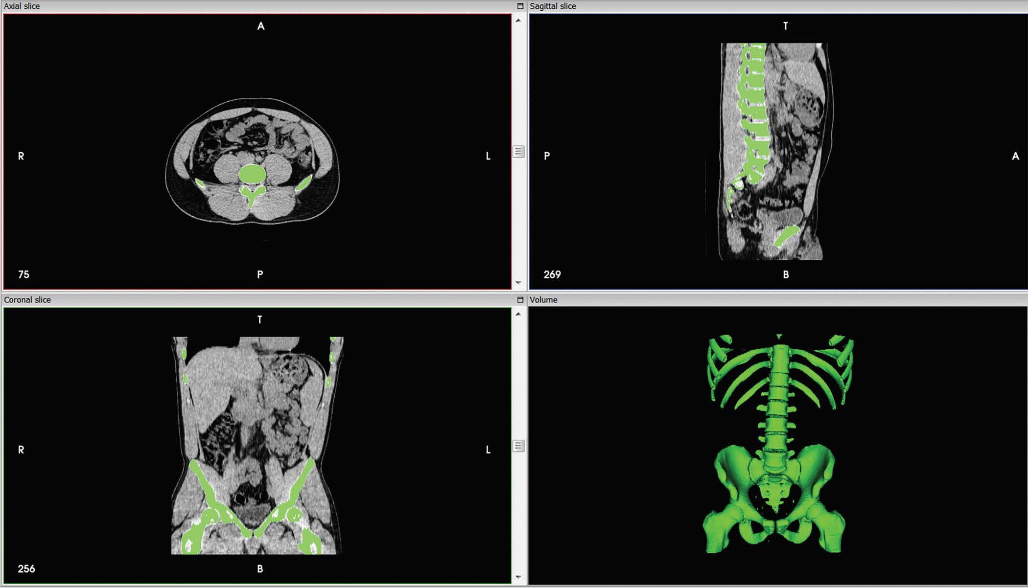
Automatic Segmentation
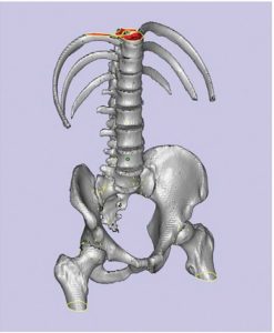
This is usually found in segmentation software like Vital Images Vitrea Advanced Visualization. It uses advanced algorithms to automatically or even semi-automatically separate specific organs from surrounding tissues. Certain methods used for automatic segmentation are, region growing, region shell, digital, subtraction and seed growing. Predefined algorithms based on the anatomy of interest, is used by auto-segmentation software to allow the user to select which region to segment. The 3D models derive from both the automated and interactive segmentation tools. Multiple anatomic regions can be combined from the models. Furthermore, they are exported as an STL file for additional refinement and 3D printing. Arterial phase volume showing the arteries and a venous phase volume showing the veins are used when segmenting 3D models.Thresholding
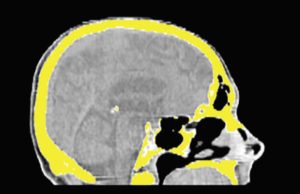
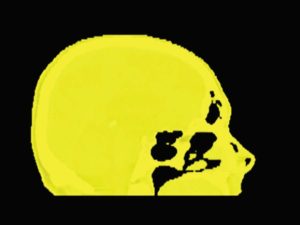
This is typically used within scans where certain anatomies have distinct sets of values, such as a high contrast By keeping certain values of the medical image, we are given the capability to visualize a specific part of the body, like bones. Using the skull example, we’d like to isolate only the bone data.Keeping in mind that in CT images, the pixel value represents the density, keeping only the brighter pixels left on the bone.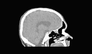
- OsiriX
-
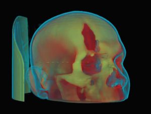
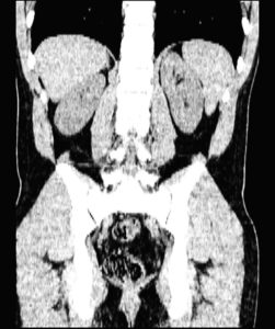
Contrast & Windowing
A large range of data is contained within a scanned image. An example of this would be values which hold ranging from -2408-1600. If the entire range was shown, all tissues scanned like the muscle, fat, and hard cortical bone will appear. In order to visualize and capture more subtle differences within specific organs or tissues, correct or change how the image is displayed.
In order for visualization to be enhanced, indicate the intesity of the data you seek, and the amount you’d like to be shown. Usually, parameters that appear in DICOM segmentation/visualization software control the appearances of the following models:
- White level – tells you which level is rendered on screen as white
- Window size – indicates values shown on-screen. Black or white will be every value outside the window.
Begin by finding the value of the tissue you’re trying to visualize. Then, set the window size to the smallest value which clearly indicates the boundaries.

-
Preparation for 3D Printing & Data Optimization
To minimize the exposure to potentially harmful radiation and reduce scan time, medical imaging experts use many different scanning protocols. What varies between scans is the slice height. This is how space is represented – in millimeters, between two images in the DICOM set. Values usually range from 0.3-0.7 mm (300-700 µ). Because PolyJet™ 3D printers have the ability to build with slice heights of 16-30 µ, the data will require optimization before 3D printing occurs.
Smoothing
Several slices from DICOM data are taken when smoothing to create additional slices between them for 3D printing.
Data Acquisition Best Practices
Original data plays a part in the final product (such as a 3D printed surgical planning model). The final product is affected by the following things:
- Use of contrast to enhance the anatomy
- Image resolution
- Software sophistication
The following recommendations is used in order to achieve the best data possible
In order to improve the final result and decrease the length of time to prepare 3D products, ensure you have Good CT, MR and 3D X-ray datasets. The best outcomes include thin-sliced CT datasets, good contrast enhancement and low-noise images.
Simpler segmentation using digital subtraction or multi-phase fusion become simpler with dual phase or multi-phase CT datasets. 3D MRI high-resolution datasets contribute to better results comparing to thick-slice MR series
To a certain degree, Vitrea Software’s 3D noise reduction, otherwise known as SPD, has the ability to be used on-the-fly in order to better the segmentation of a very noisy dataset
When using a challenging multiple-part segmentation, begin segmenting the better contrasted parts. This would include cardiac blood pool or even metal implants. Then, the low-contrast parts follow (myocardium, low-density bones)
-
3D Printing Best Practices
Additive manufacturing can be done on an endless amount of technologies. Popularly, Stratasys emplys FDM® and PolyJet. Each material contains both strengths and weaknesses in relation to medical models. FDM gives you the opportunity to print 3D parts in a broad spectrum of well-tested plastics. Where as PolyJet provides the medical world with a range of colours, mechanical properties and the ability to print in flexible, translucent materials. The chart below presents the two technologies appropriate material choices in regards to medical modeling.
Printing Technology And Material Selection
Technology Material Sterilization Methods Biocompatiable Flexible Multi-material Translucent Full Colour FDM Thermoplastic EtO Gamma Autoclave (ULTEM ™ 1010 and 9085 resin PS-ISO ™
ULTEM 1010 resin
ABS-M30 ™No No No No PolyJet Photopolymers EtO Gamma MED610
MED620
MED690Yes Yes (Connex ™ amd Stratasys J750 ™ ) Yes Yes (Stratasys J750)
FDMFused Deposition Modeling comes with specialized properties such as durability, electrostatic dissipation, translucence, bio-compatibility, UV resistance, V-0 flammability and FST ratings. Slice heights can range between from 0.127 mm – 0.256 mm. This also depends on the machine and material combination.
Design Considerations (Pre-Print)
The build orientation extremely affects the surface finish so when placing the part for build, consider critical surface and orient along the Z axis in order to gain a better appearance.
Minimize the Z height for the fastest building time if possible.
When orienting the part, consider support removal
If or when dealing with hollow parts, where breakaway support tends to be more difficult to remove, choose a material or machine combination that is compatible with soluble support material.
FDM Model And Support Material Compatibility
Soluble Support
SR-20 SR-30 SR-110 SR-100 ABSplus X ABSi X ABS-M30i X X ABS-ESD7 X PC-ABS X PC X PC-ISO ASA X Nylon 12 X PPSF/PPSU ULTEM 9085 ULTEM 1010 PolyJet – Design Considerations
Depending on the printer of your choice, PolyJet technology allows the creation of models using either single materials or multiple materials. The best materials when developing bone and similar hard structures is materials from the Vero ™ family. Tango™ and TangoPlus™ materials are used to replicate soft tissue and vasculature. In order to approximate materials of intermediate hardness, use digital materials. To reduce cost, design single-use parts of a surgical mode so that they can be inserted into a durable reusable frame. Thus meaning the part being used will need to be reprinted each time. For example, a nasal passage model (consumable) that’s inserted into a rigid model of the head.
To achieve mesh smoothing, sue Meshmixer (meshmixer.com). This is a free Autodesk software application.
Segmenting data with a PolyJet printer requires parts to be exported and reimported as an assembly. (example pic)
When preparing to print the part, ensure to select “insert assembly”
Making Transparent Parts
The appearance of VeroClear™ can range from transparent or translucent. To improve transparency, post-process, ensure the surface is as smooth as possible without affecting the clinical realism prior to printing. Transparency becomes worse when there are numerous surface artifacts.
Delicate geometry can be embedded in a clear model to make it more robust. Excessive amounts of VeroClear can reduce visibility, although polishing enhances clarity.
Sanding
Sanding enahnces the clarity of the model. It does this by smoothing the surface and removing imperfections. The following sanding stages could be performed for optimum results:
Dry Sanding: Sand dry surfaces with 200-grit sandpaper and to further improve the clarity, sand again with 320-grit sandpaper.
Wet Sanding: Only use if sanding leaves scratches on the model. Use 400-, 600- and 100-grit wet sandpaper
Micromesh sanding: Use 1500-grit and finer sandpaper for a very smooth and polished finish
Polishing And Buffing
Apply a polishing compound like 3M Plastic Polish to a buffering wheel or polishing tool. Work the above polishing tool into all surfaces of the model, then buff off the compound with a soft cloth or clean buffing pad. Lastly, to enhance clarity, spray a thin layer of lacquer.
Printing Vascular Structures
PolyJet’s rubber-like material, Tango, makes it popular when 3D printing vascular structures. Follow the recommended rules to ensure durability and the ability to clear the lumens of support material:
Internal cavities are recommended to be 2 mm or more
Wall thickness should be 1.5 mm or greater
Models deploying a narrower lumen or thinner walls can become challenging to clean without it being damaged. Offset the external surface to create the required thickness if the model is not thick enough.
To prevent and element from floating in space and losing its shape, add support structures
If possible, remove support material from flexible vascular mode using a long, this device with a hollow lumen that can aspirate to clear the channels
Build connectors to the model to enable quick connect and disconnect capability with external systems like intravenous tubing and flow pump system.
Keep in mind that when creating models that the intersection of the Vero shells and Tango material can create points of weakness
Part Cleaning
It is recommended to allow some space for the support material to expand (since it absorbs water) when using SUP706 soluble support in conjunction with flexible TangoPlus. Use a sharp elongated tool to debulk the material before soaking it in NaOH (sodium hydroxide) solution.
The “Lite Grid” support option option to allow easier support removal. Also use an iterative process of washing with low pressure water, removing free support material to assure cleaning of support from flexible vessels. High pressure water jets may rupture the vascular wall.
Models should not be soaked for more than a few hours at a time. This is because the support material tends to absorb water and swell. When facing a complicated geometry, remove a bit of support to allow a place for expansion.
It’s best to avoid sharp corners where possible. Use local smoothing to create smooth transitions around corners.
- Company
- Products
- Manufacturing Services
- Resources
- Why Silicone 3D Printing?
- Fuse 1 | SLS Design Guidelines
- Technical Support, Repairs for 3D Printing, CNC Milling, 3D Scanning
- Terms and Conditions – Annual Maintenance Contract Proto3000
- Billable Technical Support & Repair Services
- Proto3000 Webinar Series
Skip to content
