The following tutorial shows how to print full textured CAD files encased inside transparent blocks. This helps support complex parts, show vistas, or even increase the usability of your full-colour models.
Step 1: Overview
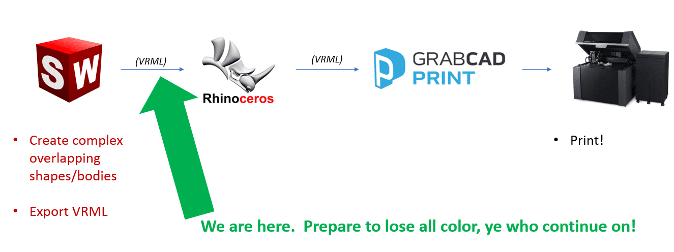
In order to print texturized bodies inside clear blocks, the general workflow will be:
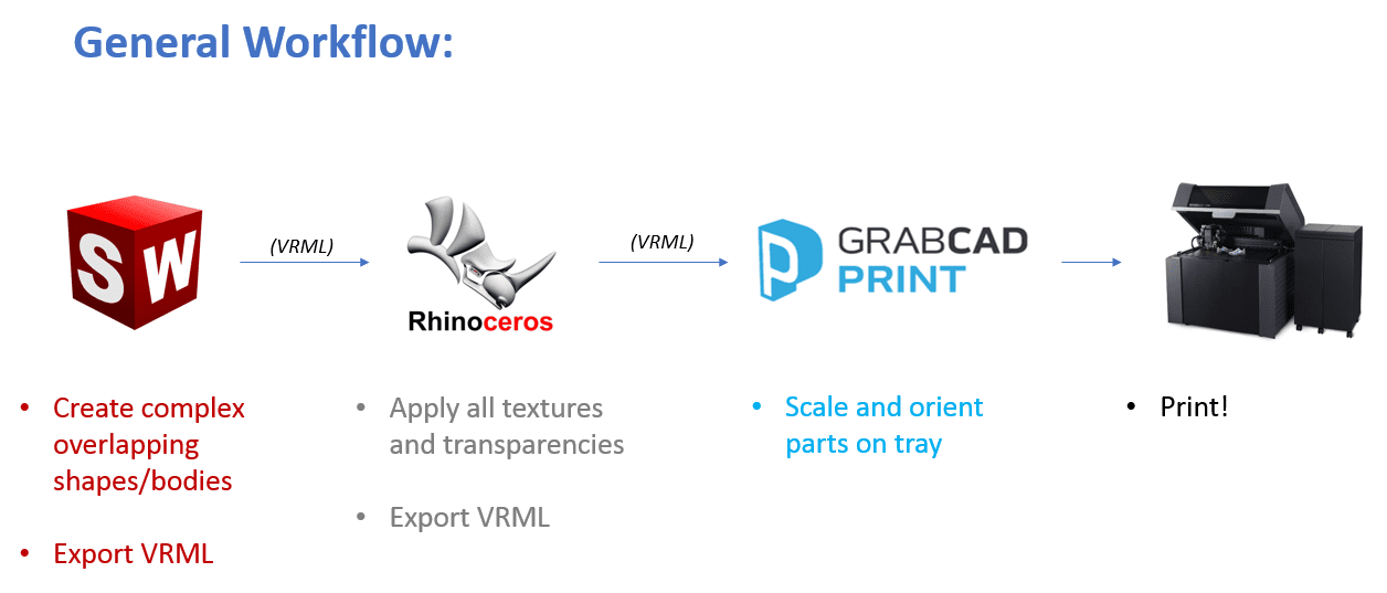
Readers who are Rhino experts can cut the SOLIDWORKS step and create their shapes in Rhino, however, this workflow matches the following skillset. Just to be clear, if you use SOLIDWORKS commonly:
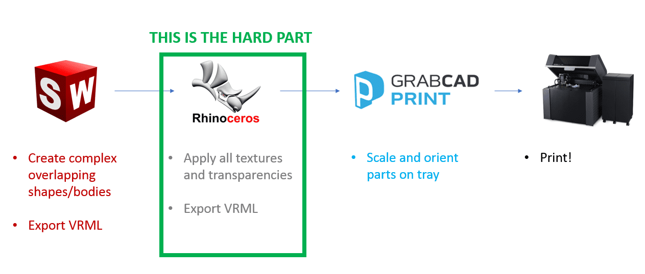
You’ll probably already know how to do everything outside of that green box, so this tutorial will focus on how to deal with, and how to prepare the textured, overlapping VRML for GrabCAD Print.
The first thing to do is to be able to comprehend what Booleans are and why they have been used. Let’s begin.
Step 2: Why Aren’t Booleans Required? And What Are Booleans?
The major enabling technology for textured parts inside blocks is Stratasys’ new Advanced Sliver. Boolean operations between the part and the clear volume surrounding it is no longer required. Here is what the situation previously looked like:
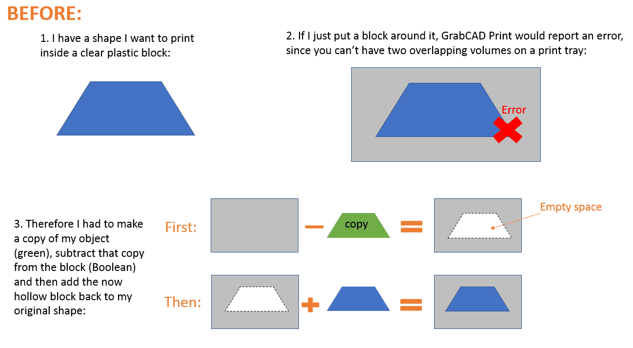
Though it may seem easy for the simple shape shown above, however as you receive more bodies in your model, some with badly defined boundaries (which happens with a lot of medical scans), the Boolean operations get a lot more difficult.
By doing the booleans with textured bodies was only successful in a few software, limiting what types of things could be 3D printed inside of clear blocks (and by whom).
Thanks to Stratasys’ Advanced Slicer, you don’t have to do those Booleans at all. Now the Slicer recognizes the larger block should automatically make up the pace for overlapping volumes inside of it:
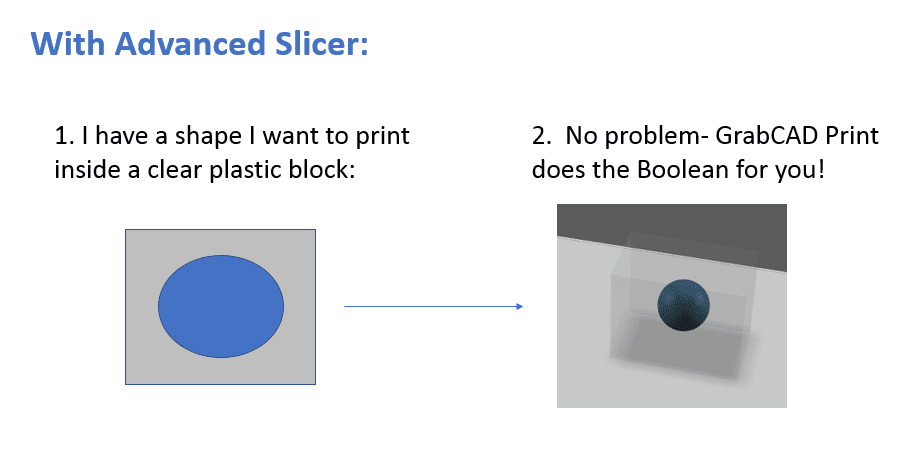
This makes things much easier. So now, focus on making overlapping volumes in SOLIDWORKS, before exporting to Rhino for texture mapping.
Step 3: Making Your Overlapping Volumes
During this section of the tutorial, an example of a print cutaway view of a rocket will be printed. It’ll begin with the below model of an AGM-84 Standoff Land Attack Missle( SLAM) from the GrabCAD Community. Here is how it looks starting off in SOLIDWORKS.
We can easily extrude a rectangular block around that missile and be done, which could be a good test for most users to do in order to test the process of importing overlapping volumes for printing. However, we can make things nearly 20% cooler.
Like some community models, this model is fully solid inside. But let’s hollow it out and add missile guts using SOLIDWORKS to make things more exciting!
Typically, missiles have payloads and guidance electronics, so let’s add those too. Thin, slender shapes are required to get braced, so let’s add a bunch of brace rings for no reason.
Although these bodies don’t have anything to do with the accuracy of the missile in real life, they do require caring about whether they interfere with one another or not. Look at how the brace rings dive into the rocket body. Before the Advanced Slicer, clean all the overlapping volumes prior to GrabCAD Print accepting it.
Some of those bodies are currently overlapping, but let’s add the large clear block around all which interferes with everything, to encase the print. Since you want people to get closer to the cutaway, make your clear body have a cutaway too.
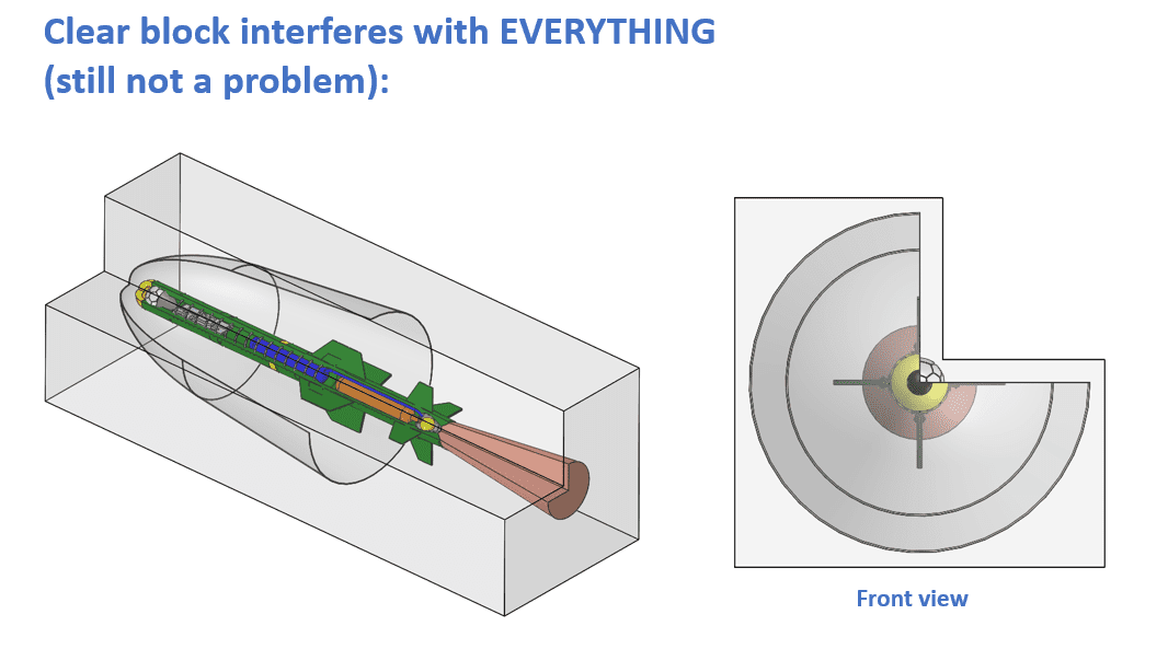
There’s a bit of time that’s been spent on making the colours of the SOLIDWORKS bodies close to what is desired in the final print (mainly for the benefits of these screenshots) but exporting colours and textures out of SOLIDWORKS is always dicey. So even though this will be saved as a VRML, you’ll see it lose all its colours when it imports into Rhino.
Step 4: Adding Colour And Textures In Rhino
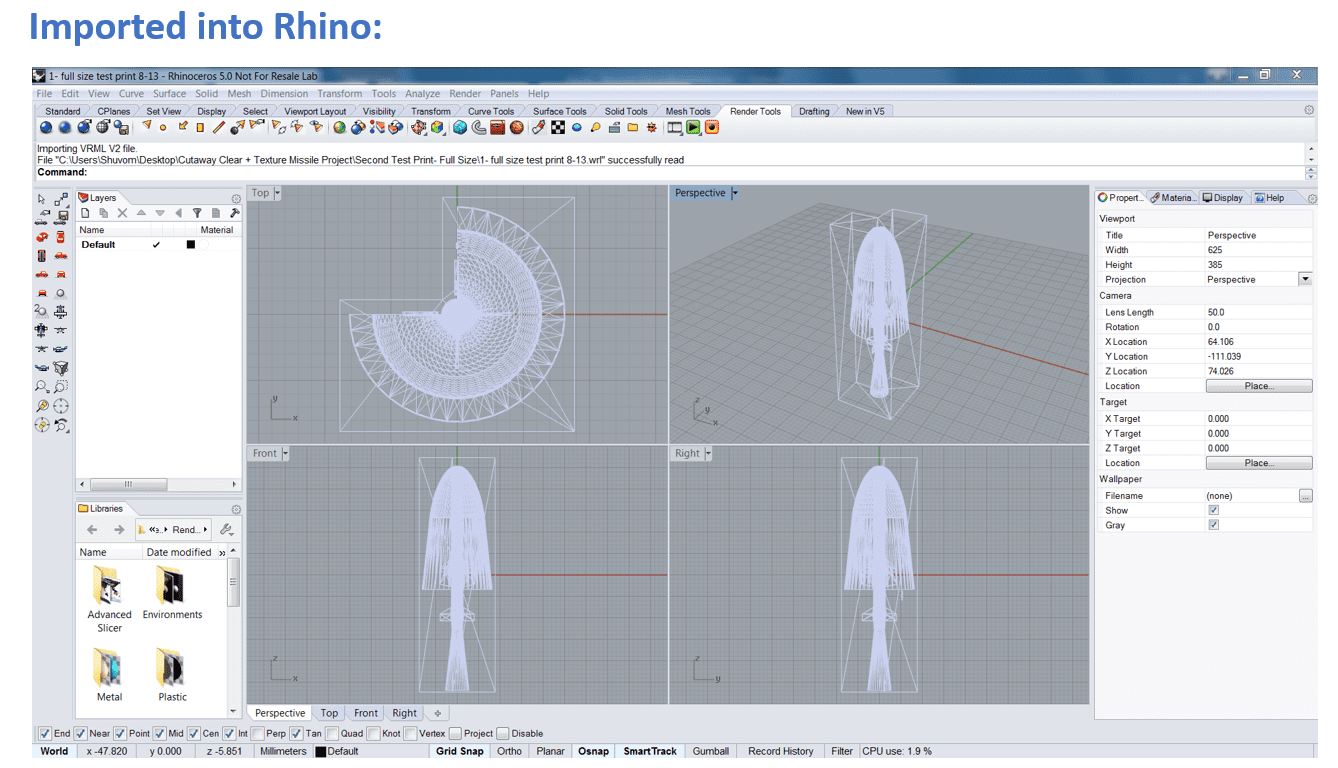
This is how the nicely coloured, high-resolution SOLIDWORKS model looks when the VRML is imported into Rhino.
Even putting the viewpoint to “Rendered Mode” does not restore any o the cool colours added in SOLIDWORKS.
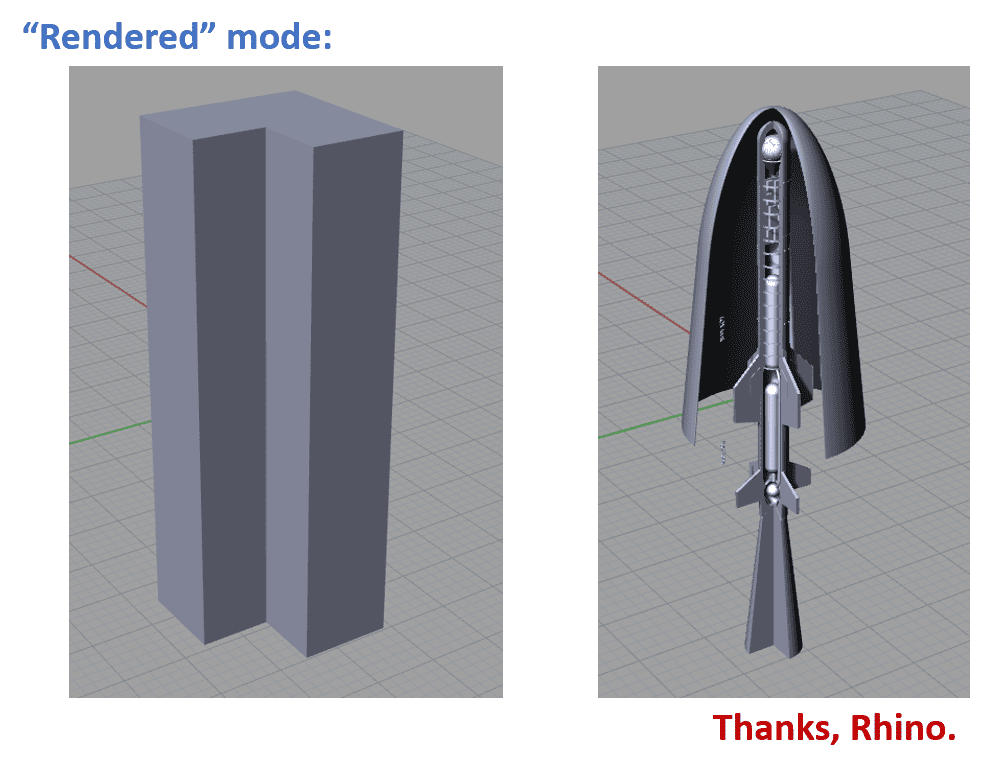
With no one to blame, blame bad VRML exports from SOLIDWORKS and bad VRML imports to Rhino. It seems as though the single SOLIDWORKS part colour gets propagated down to all bodies, regardless of body or face colour applied in SW, however, it doesn’t matter because we will re-colour everything in Rhino anyway.
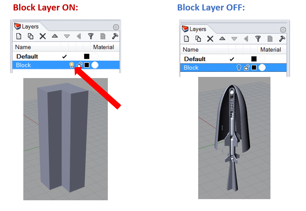
NOTE: To make your life easier, use layers in Rhino.
Users have the ability to select any given body in their Rhino model. Right-click on a layer, choose “Change Object Layer” to move to the current layer. That’s how the picture above was made, putting the outer block on its own layer and easily hiding it for the image:
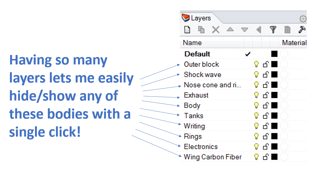
Typically, make a layer for each sub-group that will be coloured/textured, since you want to ONLY see that group when applying textures.
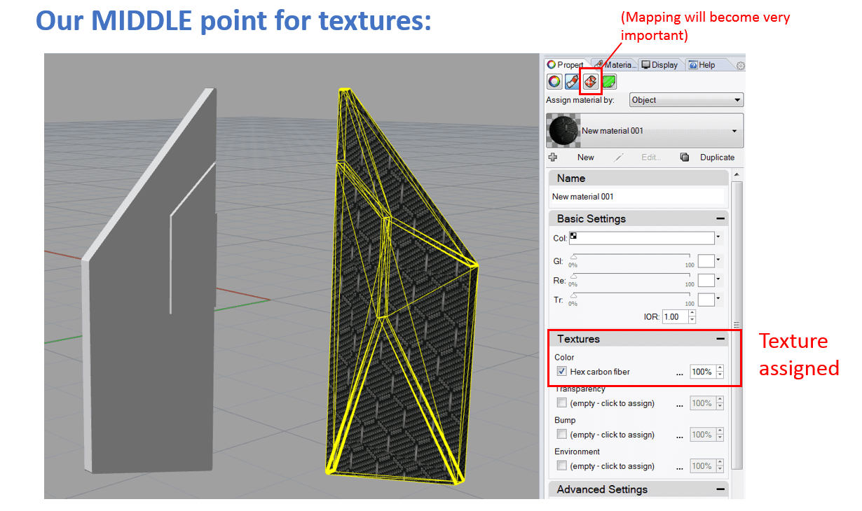
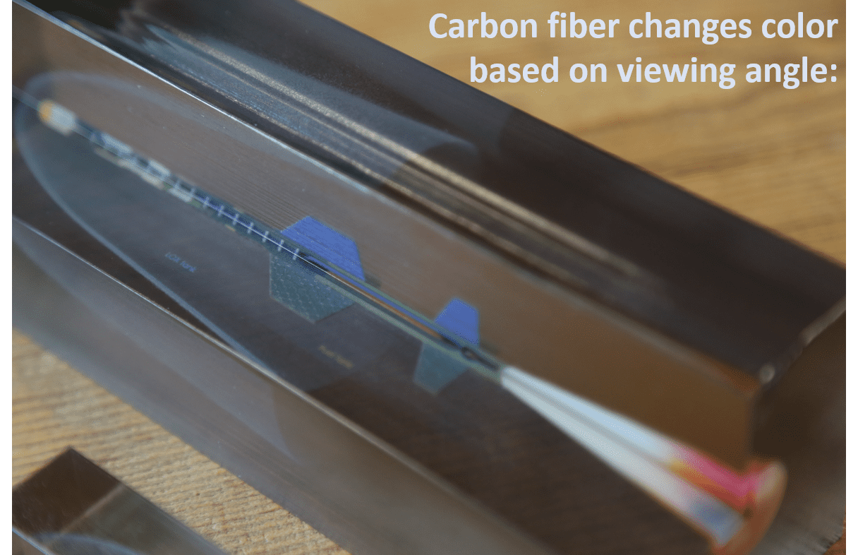
Now that you have the layers, here is the texturing for ONE body. The same logic will apply to all bodies in the print. Begin with the wings:
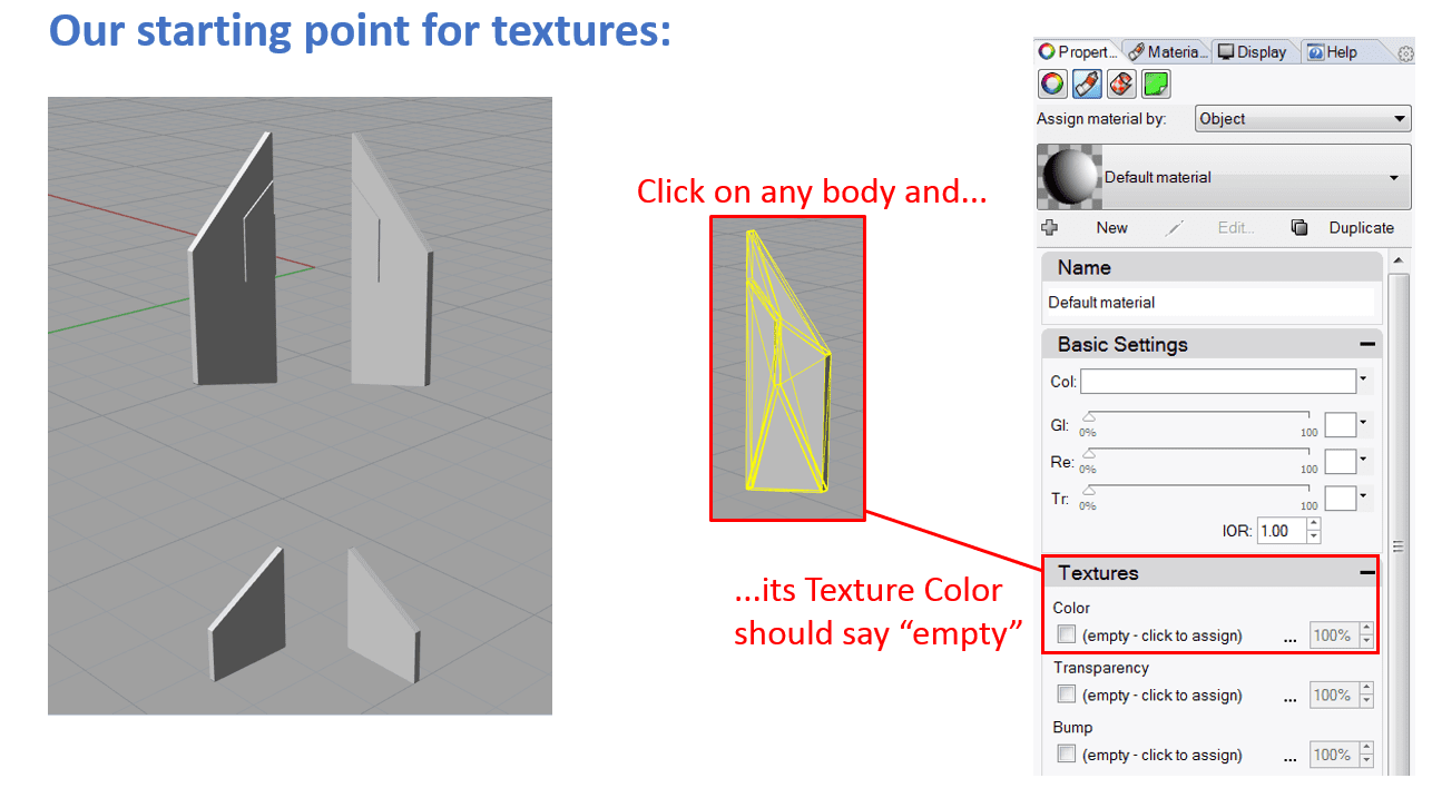
Click the “empty – click to assign” link and select your swatch. Act as if these wings have carbon fibre inside, so choose a swatch that looks as it does below:
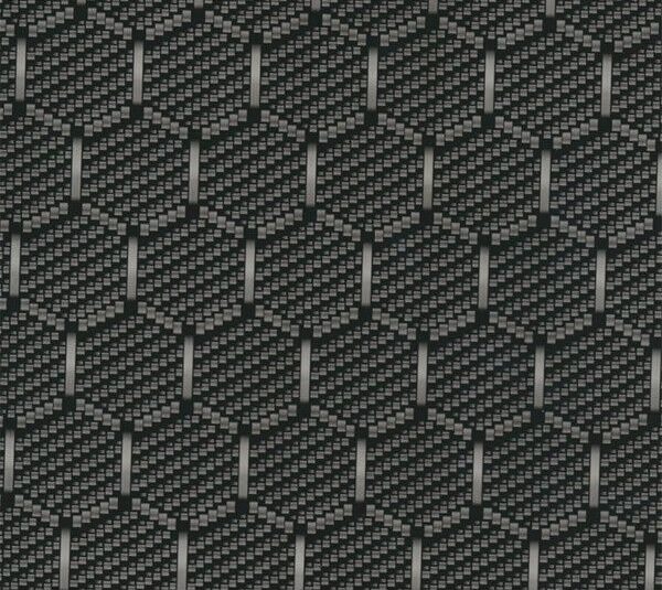
NOTE: It is CRUCIAL that this swatch is in the same folder as the VRML you will eventually save out of Rhino. If the texture is not in the same folder as your VRML, GrabCAD Print cannot find it and your entire model will come out solid grey (see ‘troubleshooting’ later on in the tutorial).
Because of this, CAD, Rhino, and texture files all in one folder are kept together for a print. Rarely use the stock Rhino textures, which can typically be hidden in some install directory somewhere.
At this point, your model should look similar to this:
These textures are pointed out not for the fun of it, but because if you’re not doing this level of texture mapping inside you’re models, you’re not truly using the full power of a printer like a J750. Many printers can do single colour prints, such as the fuel tanks above. A few can do textures, however, very few can do colours and textures in six different materials perfectly encased inside a clear plastic block, at a resolution a quarter the thickness of a human hair. What a time to be alive!
Since our textures are set, it’s time to get to the last step in Rhino: ensuring there is a transparent outer block.
Step 5: Transparency In Advanced Slicer Prints
Following are the rules of transparency:
- Any VRML coming out of Photoshop with even ONE transparent pixel in its wrapped texture will make that body fully transparent in the Advanced Slicer. Making the body bulk transparent is not necessary.
- VRML bodies out of Rhino require bulk transparency set to 100% to be read as transparent by the Advanced Slicer.
This all comes down to the various programs that write VRMLs. Some software users use to texture map VRMLs, such as Magics, could potentially be different. Those are the rules as of GrabCAD Print version 1.20 which was released July 18th 2018. As things change, we’ll see this paragraph here. So in the rocket, there are two transparencies:
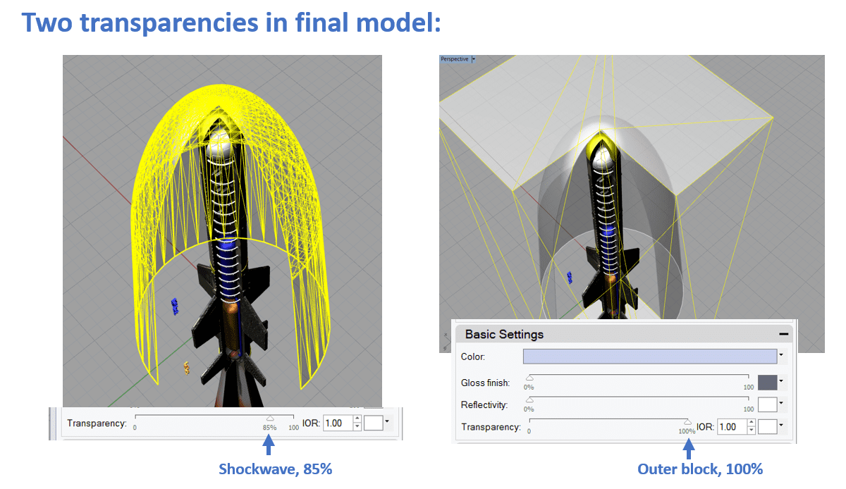
At first, it was unknown if the Advanced Slicer could handle the mixing transparencies on different bodies, however, it was able to handle it quite well.
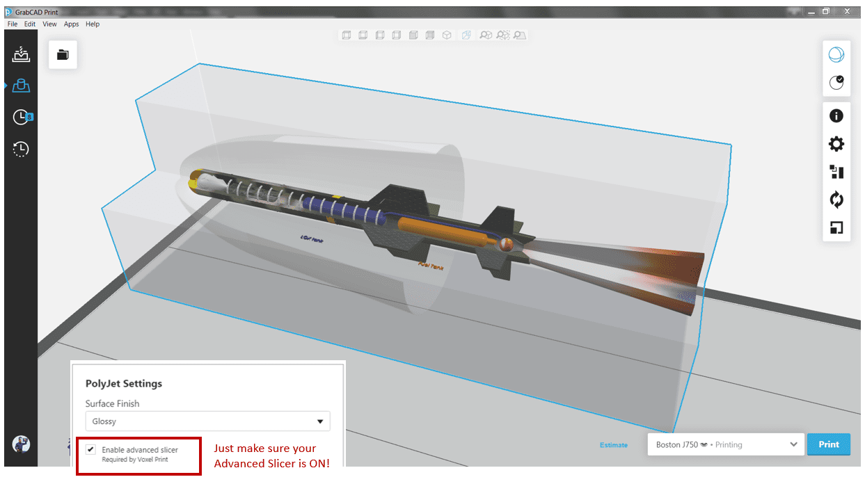
After setting up your outer block to 100% transparency, you can “Save As…” a VRML and open it right up in GrabCAD Print:
This is if everything goes well. Before showcasing the finished model, let’s talk about the possible things that could go wrong.
Step 6: Troubleshooting Texture + Block Prints
Common Error 1: Missing Textures
The most common thing that went wrong here was opening a model in GrabCAD Print and seeing the following:
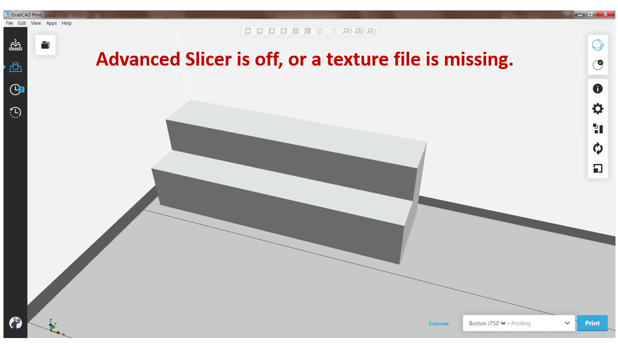
This generally occurs if even ONE out of fifty textures flies is missing. Keep all necessary texture files in the same folder as the VRML, since that’s where GrabCAD Print looks.
Common Error 2: All VRMLs Should Share The Same Core
After squaring all the texture paths away, opening the 262 body VRML inside GrabCAD Print may give you this:
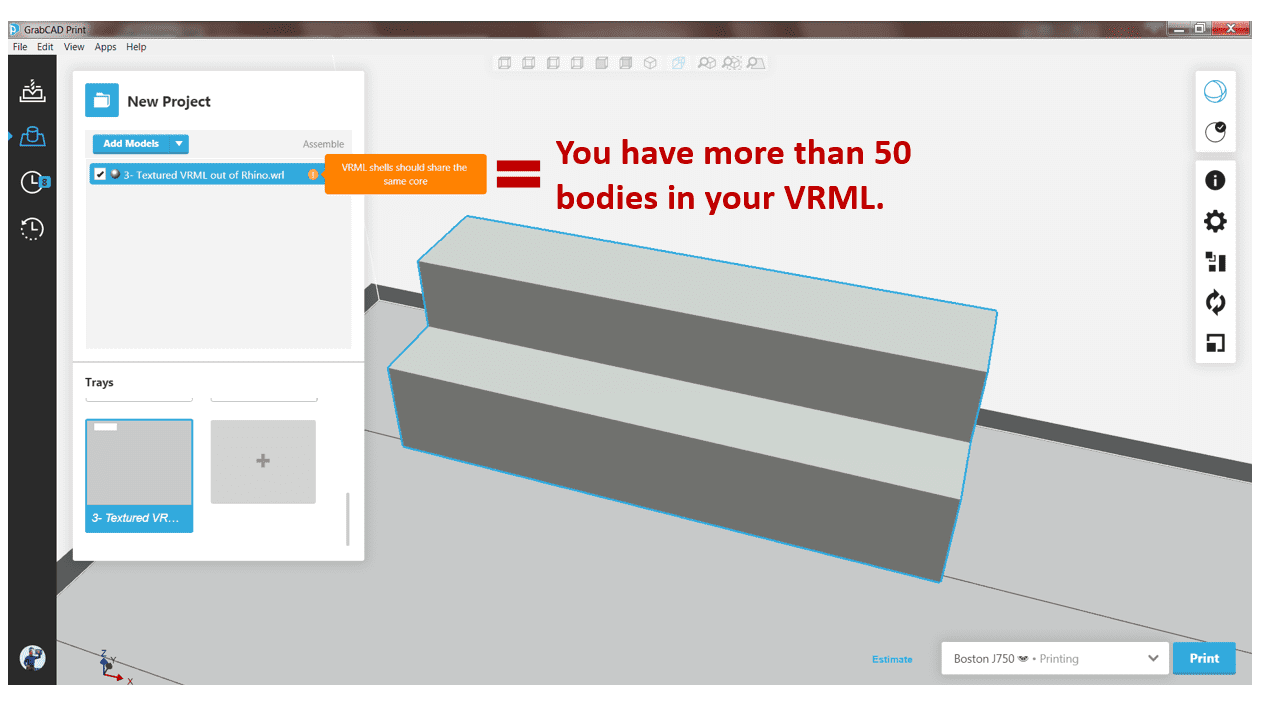
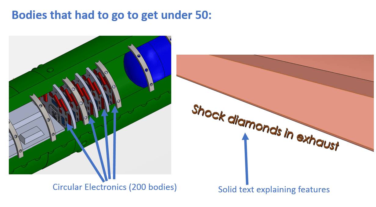
The error here looks similar to the first error. There is a current rule hardcoded inside the Advanced Slicer that can have a maximum of 50 separate solid bodies in your VRML prior to the slicer giving up trying to boolean them and says “Fine, I guess they’re all surface bodies in one big VRML!”. In some applications, this can be a positive thing, however not in this one. This is a shame due to the removal of a lot of interesting bodies to get under 50.
Common Error 3: Textures Aren’t “Clamped”
Bad handoff between Rhino and GrabCAD Print is the last common error. This is usually noticed first when opening your model and the carbon fibre wings which looked okay in Rhino now looks like this:
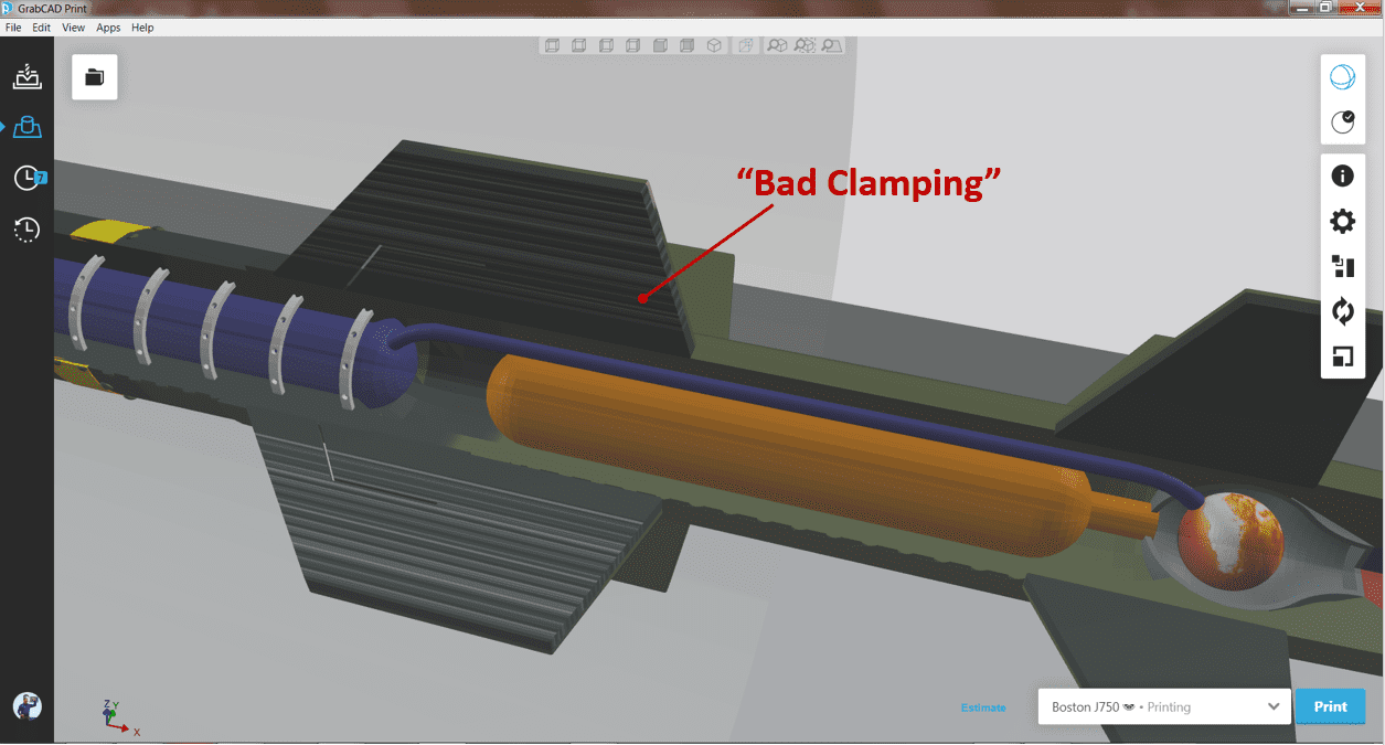
To be clear, this error occurs when texture mapping looks okay in Rhino, however, seems hyper stretched when opening in GrabCAD Print. What happens is that the texture ends halfway across your physical body and GrabCAD Print attempts to “clamp” down on one end of your texture and stretch the last line of pixels to “fit.”
There’s most likely some setting about “Clamping” or “Repeating” that could have been changed in Rhino. But one of the gurus suggested opening the VRML in a notepad and change “Repeats” of the affected textures from “False” to “True”.
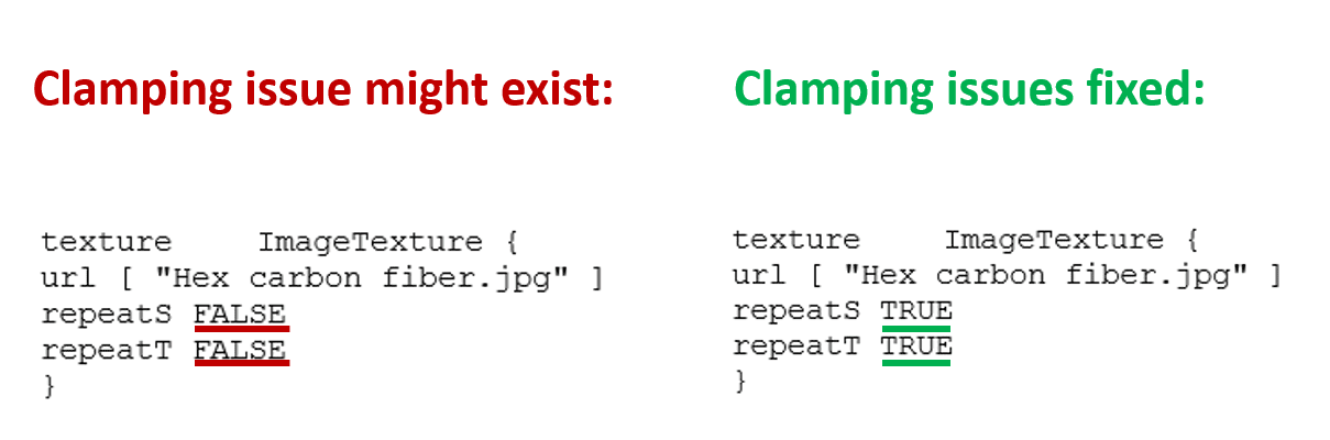
If you can not figure out Rhino clamping settings, feel free to use it as well. You do have to do it for each affected body in the VRML, so 4 wing bodies for here. Now, let’s get to the fun part – results!
Step 7: Results
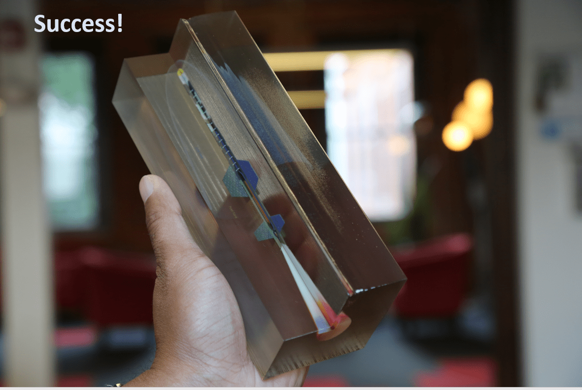
Though it is not fully sanded or clear coated, it still turned out pretty good, especially the carbon fibre.
The transparency right on the shock wave:
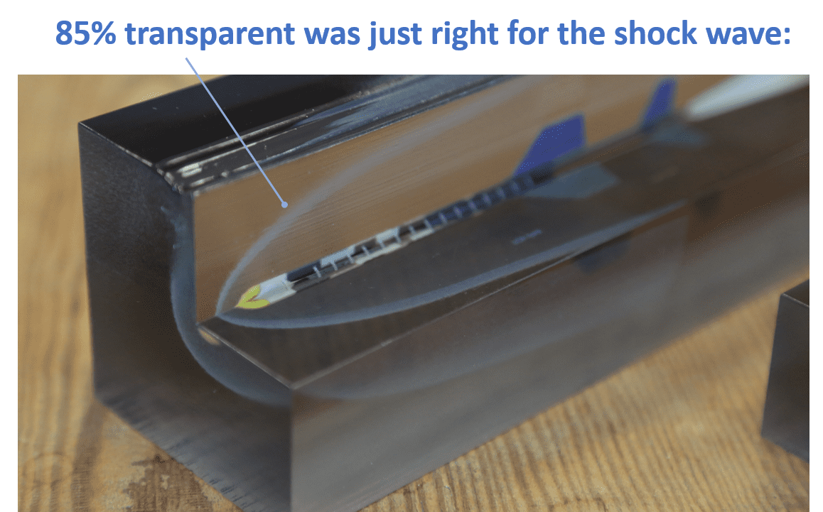
For the most part, this is great for a second draft. It’s suggested printing a smaller version of my texture-inside-block print first because if there are errors, you’d want to catch them on a three-hour build compared to a nine-hour build.
That is an amazing result, however, there is more we can do to enhance this print.
Step 8: Further Optimizations
Below are optimization tips for your texture-in-block prints:
Optimization Tip 1: Choose Printing Orientation For Best Quality
Frequent PolyJet users know clear prints are clearer when looking down one axis versus another, but just in case there are some new J750 users here:
Orient your block so the faces you want most clear are visible looking down the Z axis.
This is why, for the third draft model, there are some suggestions listed and the rocket is cut in half instead of 3/4ths, printing the main faces in the “More Clear” direction and things turned out better:
The half-cut is the keeper. The electronics are visible, as well as the payload, the shock diamonds – everything! So keep in mind to continue iterating on prints even after they look good.
Preparation Tip 2: Increase Thickness On Thin Textured Bodies
As an example, here is a comparison of FDM and PolyJet layer heights.

This model was printed in High Mix Mode to save printing time, meaning the layers were 0.027 mm (27 microns thick). When the SOLIDWORKS missile was originally hollowed out and did the three-hour test print, the wing sections were 0.23 mm (8 layers) thick.
This missile’s body was also only 0.35 mm or 12 layers thick, and you could basically see through the camouflage!
So for the official print, which is twice as large, the thickness in SOLIDWORKS was also increased so that in the final print, there will be about 30 layers for the wings and 50 for the missile body, and now those sections seem more solid.
Keep in mind that the goal here is not for the measurements to be “official”, but for it to look food in the final print. Generally, this is done mostly on architectural prints. Real size windows and walls which are scaled down to fit your printer, are almost non-existent.
Thicken the thinner bodies. 3 mm thickness is the requirement for a two-sided texture body to achieve true, solid colours.