-
Introduction
Elastic ToughRubber™ (ETR) unlocks the benefits of additive manufacturing for the rubber, polyurethane, and foam industries. ETR 90 Black is a high strength rubber, which makes it great for applications like vibration-dampening components, seals, and baffles.
This material is available in two colours:This material is tested and approved for use only on ETEC®’s Xtreme 8K DLP 3D Printer.
-
Design Parts for Elastic ToughRubber 90
Tip
Place parts with large flat areas on supports rather than on the build platform to improve the part removal process.
It is recommended to add channels or drainage holes to hollow parts. This allows uncured material to drain from the hollow feature during printing.
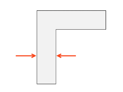
Minimum Wall Thickness
Minimum Feature Size
- is dependent on:
- specific 3D printer
- material
- feature geometry
important
Min. feature sizes are only valid for smaller features within the part geometry (e.g. text, small channels, etc.) They should not be used for the main components of design methodology.
- is dependent on:
-
Min. Feature Sizes
ETEC recommends the following min. feature sizes for parts printed in ETR 90 Black:
Design Feature Minimum Recommended Engraving Depth (XY) 0.15 mm Engraving Depth (Z) 0.15 mm Embossing Height (XY) 0.15 mm Embossing Height (Z) 0.15 mm Positive Features (XY) 0.30 mm Positive Features (Z) 0.45 mm Negative Features (XY) 0.30 mm Negative Features (Z) 0.45 mm Unsupported Walls 0.60 mm Supported Walls 0.45 mm Clearance Between Mating Features 0.45 mm Hole Diameter 1.50 mm Wire Size 0.60 mm -
Lattice Design
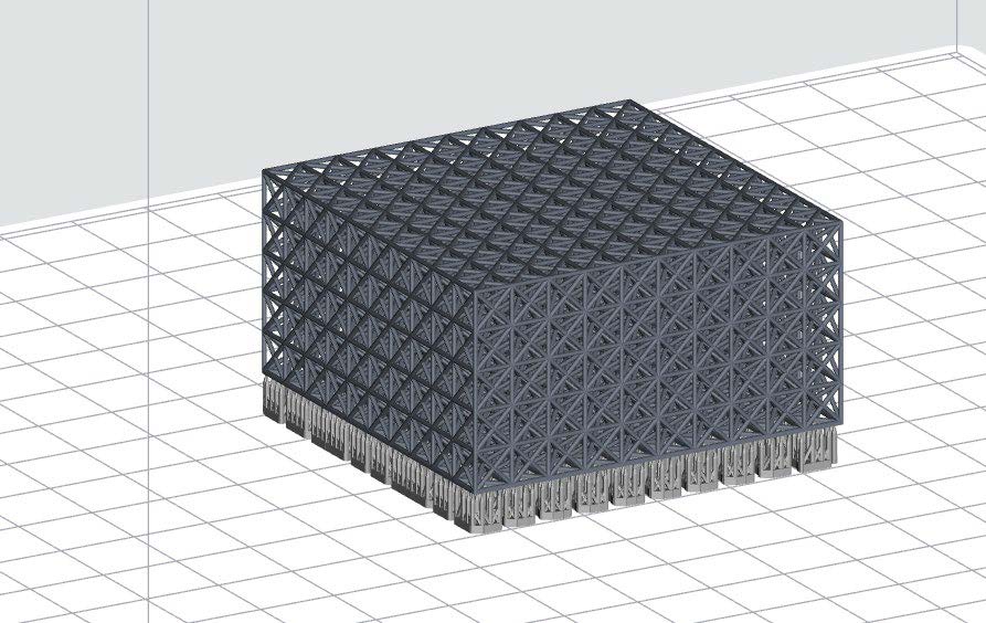
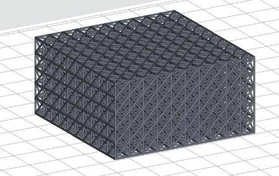
Lattice structures are comprised of cells and struts. The recommended cell size is dependent on the strut size and vice versa.
Body-centered cubic (BCC) lattice size recommendations:
Strut: 0.50 mm Strut: 0.75 mm Strut: 1.0 mm Strut: 1.5 mm Cell: 2.0 mm 2.0 mm x 0.50 mm
recommendedCell: 4.0 mm 4.0 mm x 0.50 mm
recommended4.0 mm x 0.75 mm
recommended4.0 mm x 1.0 mm
recommendedCell: 6.0 mm 6.0 mm x 0.50 mm
recommended6.0 mm x 0.75 mm
recommended6.0 mm x 1.0 mm
recommended6.0 mm x 1.5 mm
recommendedCell: 8.0 mm 8.0 mm x 0.50 mm
recommended8.0 mm x 0.75 mm
recommended8.0 mm x 1.0 mm
recommended8.0 mm x 1.5 mm
recommendedCell: 12.0 mm 12.0 mm x 0.75 mm
recommended12.0 mm x 1.0 mm
recommended12.0 mm x 1.5 mm
recommended -
Self-Supporting Angle
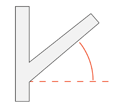
The maximum self-supporting angle for parts printed in ETR 90 Black is 75° from horizontal. Angles as shallow as 30° may be printed without supports, but some deformation can occur.
-
Unsupported Overhang
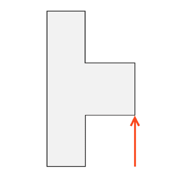
The maximum unsupported horizontal overhang for parts printed in ETR 90 Black is 1.50 mm.
-
Software | Print Preparation
Orient Parts in EnvisionOne RP Software
Envision One RP automatically orients your model, adds supports, if necessary, and sends the file to the printer, resulting in your three-dimensional model. Everything that is printed using ETEC printers must pass through this software successfully.
- Spacing: Place parts a minimum of 2.050 mm apart.
- Level at build platform: Place unsupported parts directly on the build platform. Place supported parts 10.0 mm from the build platform.
- Resolution: 150 µm Z resolution (dependent on layer thickness).
-
Support Parts | EnvisionOne RP Software
Some approved applications require supports. You can always use the ETR90-Black .ini support file:
- Minimum support base: 1.60 mm
- Minimum contact tip: 0.40 mm
- Minimum support beam height: 10.0 mm
